
User Manual


Annex page 2 of 7
Annex to Test Certificate No. DK0199-R76-11.10
Issued by DELTA
•
Weighing unstable samples
• Totalisation
3. Technical data
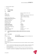
3.1 Indicator
Type KFA-TM / KFE-TM / KFC-TM
Accuracy class III or IIII
Weighing range Single-interval, multi-range or multi-interval
scale intervals (n) 6000 or 2×3000 for class III,
1,000 or 2×1000 for class IIII
Minimum input voltage per VSI 1 µV
Maximum capacity of interval (Max
i
): n
i
× e
i
Verification scale interval, e
i
= Max
i
/ n
i
Initial zero-setting range: ± 10 % of Max
Maximum tare effect: 100 % of Max
Fractional factor (pi) 0.5
Excitation voltage 5 VDC
Circuit for remote sense Not active
Minimum input impedance 350 ohm
Maximum input impedance 1200 ohm
Connecting cable to load cell(s): See Section 3.1.1
Supply voltage: 9-12 VDC
Operating temperature range Min / Max = -10 °C / +40 °C
Peripheral interface(s) See Section 4
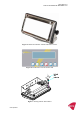
3.1.1 Connecting cable between the indicator and the junction box for load cell(s),
if any
3.1.1.1 4-wire system
Line 4 wires, shielded
Maximum length The certified length of the load cell cable, which shall be con-
nected directly to the indicator.
4. Interfaces
4.1 Load cell interface
Refer to section 3.1.1.
Any load cell(s) can be used for instruments under this certificate provided the following conditions
are met:
• There is a respective test certificate (EN 45501) or an OIML Certificate of Conformity (R60)
issued for the load cell by a Notified Body responsible for type examination under the
Directive 2009/23/EC.
• The certificate contains the load cell types and the necessary load cell data required for the
manufacturer’s declaration of compatibility of modules (WELMEC 2, Issue 5, 2009, section