KERN & Sohn GmbH Ziegelei 1 D-72336 Balingen E-Mail: info@kern-sohn.com Phone: +49-[0]7433- 9933-0 Fax: +49-[0]7433-9933-149 Internet: www.kern-sohn.com Operating and Installation Instructions Display Unit KERN KFE-TM Version 1.
GB KERN KFE-TM Version 1.3 06/2013 Operating and installation instructions Display unit Contents 1 Technical data ................................................................................................... 4 2 Appliance overview ........................................................................................... 5 2.1 Keyboard overview .................................................................................................... 6 2.1.1 2.
7 Operation ......................................................................................................... 18 7.1 Start-up .....................................................................................................................18 7.2 Switching Off ............................................................................................................18 7.3 Zeroing ..............................................................................................................
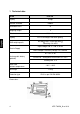
1 Technical data KERN KFE-TM Display 6-digit Solution verifiable 6.000 e Verification class III Weighing ranges 2 1,2,5,…10, n Divisions Display DMS weighing cells LCD 22 mm digits with back lighting 80-100 . Max. 4 items per 350 Sensitivity 2-3 mV/V ; Input voltage 220 V – 240 V, 50 Hz Electric Supply Mains adapter secundary voltage 12V, 500 mA 6 x 1.
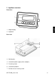
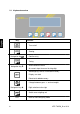
2 Appliance overview Front view: 1. Weight display 2. Keyboard Rear view: 3. Wall bracket 4. Connection power supply (mains adapter) 5. Fastening screws 6. Connection platform 7.
2.
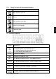
2.1.1 Numerical input via the navigation buttons Key Function Digit selection to the left Delete Digit selection to the right Increase flashing digit Terminate input 2.
3 Basic Information (General) 3.1 Proper use The display unit acquired by you is used in combination with a weighing plate and serves to determine the weighing value of material to be weighed. It is intended to be used as a “non-automatic weighing system”, i.e. the material to be weighed is manually and carefully placed in the centre of the weighing plate. As soon as a stable weighing value is reached the weighing value can be read. 3.2 Improper Use Do not use display unit for dynamic weighings.
3.4 Monitoring of Test Resources In the framework of quality assurance the measuring-related properties of the display unit and, if applicable, the testing weight, must be checked regularly. The responsible user must define a suitable interval as well as type and scope of this test. Information is available on KERN’s home page (www.kern-sohn.com with regard to the monitoring of display units’ test substances and the test weights required for this.
6 Unpacking and installation 6.1 Installation Site, Location of Use The display units are designed in a way that reliable weighing results are achieved in common conditions of use. Precise and fast work is achieved by selecting the right place for your display unit and your weighing plate. On the installation site observe the following: Place the display unit and the weighing plate on a stable, even surface.
6.4 Transit Securing Please note, if the display unit is used together with platform with transportation lock, this transportation lock must be released prior to use. See operating instructions attached to the respective platform. 6.5 Mains connection Power is supplied via the external mains adapter. The stated voltage value must be the same as the local voltage. Only use original KERN mains adapters. Using other makes requires consent by KERN. 6.
6.7 Adjustment As the acceleration value due to gravity is not the same at every location on earth, each display unit with connected weighing plate must be coordinated - in compliance with the underlying physical weighing principle - to the existing acceleration due to gravity at its place of location (only if the weighing system has not already been adjusted to the location in the factory).
Call-up menu In weighing mode press the first menu block and at the same time and will appear. Press repeatedly until is displayed. Press , password query will appear. Press , , subsequently until the first menu item is shown. Press repeatedly until Confirm by is displayed. . Press repeatedly until the currently balance typ will be displayed. = Singel range = Dual range = Multi interval Confirm by Press Confirm by .
Procedure Confirm menu setting by . Ensure that there are no objects on the weighing plate. Wait for stability display, then press . The currently set adjustment weight will be displayed. Either use the displayed adjustment weight or change it with , and (numerical input see chapter 2.1.1), the active digit is flashing. Confirm by , „LoAd“ will be shown. Carefully place adjusting weight in the centre of the weighing plate. Wait for stability display, then press .
6.8 Linearization Linearity shows the greatest deviation of a weight display on the scale to the value of the respective test weight according to plus and minus over the entire weighing range. If linearity deviation is discovered during a testing instrument control, you can improve this by means of linearization. Carrying out linearization is restricted to specialist staff possessing well acquainted with the workings of weighing scales. The linearisation is locked for verified weighing systems.
Wait for stability display „STABLE“, then press . When “LoAd 3“ is displayed, put the third adjustment weight (1/3 max) carefully in the centre of the weighing platform. Wait for stability display „STABLE“, then press . After the adjustment the balance will carry out a self-test. Remove adjusting weight during selftest, the appliance will return into weighing mode automatically. An adjusting error or incorrect adjusting weight will be indicated by the error message; repeat adjustment procedure. 6.
Position of seals and jumper Access to conductor plate: Remove seal Open display unit For adjustment / access to the configuration menu the jumper „CAL“ must be fitted.
7 Operation 7.1 Start-up Press and the instrument will carry out a self-test. As soon as the weight display appears, the instrument will be ready to weigh. 7.2 Switching Off Press and the display will disappear. 7.3 Zeroing Resetting to zero corrects the influence of light soiling on the weighing plate. To unload the weighing system Press and zero display as well as indicator ZERO will appear. 7.4 Simple weighing Place goods to be weighed on balance.
7.5 Weighing with taring Deposit weighing vessel. After successful stop check press the display and indicator NET appear. button. Zero The weight of the container is now internally saved. Weigh the material, the net weight will be indicated. After removing the weighing container, the weight of the weighing container appears as negative display. The taring process can be repeated any number of times, e.g. when adding several components for a mixture (adding).
1. Call up menu In weighing mode press the first menu block and at the same time and will appear. 2. Set limit values Keep on pressing until the display used for entering the lower limit SET LO appears. Press and current setting will be displayed. To enter the lower limit, e. g. 1000 Kg, press the navigation keys (See chpt. 2.1.1); the currently enabled digit will be flashing. Confirm input by . Select SET HI by pressing .
3. How to set tolerance weighing mode Press repeatedly until Acknowledge with is displayed. . Press repeatedly until BEEP is displayed. Press and current setting will be displayed. Select desired setting (bp 1, bp 2, bp 3) with confirm by pressing and . Press repeatedly to exit menu. The weighing system is in tolerance weighing mode, i.e. from here occurs the graduation if the weighed material is within the two tolerance limits. 4.
7.7 Manual totalizing With this function the individual weighing values are totalized into the sum memory by pressing . Menu settings: „F5 Prt“ „P prt“, see chap. 8.2 “P4 CHk“ „mode 1“, see chap. 11.4 The totalizing function is not active when the weight is under 20d. Add up: Place weighing goods A. Wait until the stability display STABLE appears, then press value is saved. . The weighing Remove the weighed good. More weighed goods can only be added when the display ≤ zero.
Delete weighing data: If you see a display of zero, press and the number of weighing, followed by the total weight will be shown for 2 sec. Press The data in the summation memory are deleted. KFE-TM-BA_IA-e-1313 during this display.
7.8 Automatic adding-up This function is used to issue and add individual weighing values automatically to the summation memory on unloading of weighing scale without pressing . Menu settings: „F5 Prt“ „P prt“, see chap. 8.2 “P4 CHk“ „mode 1“, see chap. 11.4 When function is activated, the indicator AUTO appears. Add up: Place weighing goods A. After the standstill control sounds a signal tone. Unload the weighing good, the weighing value is added into the summation memory.
7.9 Animal weighing The mean value function is suitable for weighing restless loads. Menu setting: , see chap. 11.4 When function is activated, the indicator ANIMAL appears. Place goods to be weighed on balance. When the load has somewhat calmed down, you will hear an audio sound. The mean value achieved will be shown. Whilst averaging is taking place you can add or remove loads as the measuring value will be constantly updated.
8 Menu 8.1 Navigation in the menu Call up menu In weighing mode press and the first menu block Select menu block Select setting and at the same time will appear. With help of , the individual menu blocks can be selected one after the other. Confirm selected menu item by pressing current setting will be displayed. . The Change settings To change to the available settings, press the navigations keys as described in chpt. 2.1.1.
Clk on Display time switched on After 5 min without change of load the weight display passes to the time display. Clk of* Display of time OFF bk on Background lighting of display is switched on permanently bk AU Display background illumination off bk off Automatic background illumination on when weighing pate is loaded or key pressed.
9 Service, maintenance, disposal Before any maintenance, cleaning and repair work disconnect the appliance from the operating voltage. 9.1 Cleaning Keep IP protection. Clean the stainless-steel parts with a soft cloth soaked with a cleaning agent suitable for stainless steel. For stainless steel parts do not use any cleaning agents which contain sodium hydroxide solution, acetic, hydrochloric, sulphuric or citric acid.
9.4 Error messages Error message Description ----- Possible causes Maximum load exceeded Unload weighing system or reduce preload.
10 Instant help In case of an error in the program process, briefly turn off the display unit and disconnect from power supply. The weighing process must then be restarted from the beginning. Help: Fault The displayed weight does not glow. Possible cause The display unit is not switched on. Mains power supply interrupted (mains cable defective). Power supply interrupted. (Rechargeable) batteries are inserted incorrectly or empty No (rechargeable) batteries inserted.
11 Installing display unit / weighing bridge Installation / configuration of the weighing system must be carried out by a well acquainted specialist with the workings of weighing balances. 11.1 Technical data Supply voltage: 5 V/150mA Max. signal voltage 0 15 mV Zeroing range 0 5 mV Sensitivity 2-3 mV/V Resistance parameter 80 - 100 Ω, max 4 items per 350 Ω load cell 11.
11.3 How to connect the platform Disconnect device from mains. Pull load cell cable into the display unit through the screwable cable attachment. Weld the individual wires of the load cell cable to the printed circuit board, see fig. 1. Details can be seen in the technical data of the load cell. Fig.
11.4 Configure display unit Call-up configuration menu: In weighing mode press block will appear. and at the same time and the first menu Press repeatedly until is displayed. Press , password query will appear. Press shown. , , subsequently until the first menu item is Navigation in the menu With help of other. , the individual menu items can be selected one after the Confirm selected menu item by pressing displayed.
Configuration menu overview: Menu block Main menu Menu item Submenu Available settings / explanation Not documented Single-range balance Confirm by available. , after that the following menu items are Position decimal point available selection 0, 0.0, 0.00, 0.000, 0.0000 Readability/verification value selectable 1, 2, 5, 10, 20, 50 Balance capacity (max) Adjust weighing system according to configuration. Adjustment, see chap. 6.7 For linearisation see chapter 6.
Dual range balance Confirm by available. , after that the following menu items are Position decimal point available selection 0, 0.0, 0.00, 0.000, 0.0000 Readability / verification value for 1. Weighing range Selectable 1, 2, 5, 10, 20, 50 Readability / verification value for 2. Weighing range Selectable 1, 2, 5, 10, 20, 50 Balance capacity (Max) 1st weighing range Balance capacity (Max) 2nd weighing range Adjust weighing system according to configuration. Adjustment, see chap. 6.
Multi-interval balance Confirm by available. , after that the following menu items are Position decimal point available selection 0, 0.0, 0.00, 0.000, 0.0000 Readability / verification value for 1. Weighing range Selectable 1, 2, 5, 10, 20, 50 Readability / verification value for 2. Weighing range Selectable 1, 2, 5, 10, 20, 50 Balance capacity (Max) 1st weighing range Balance capacity (Max) 2nd weighing range Adjust weighing system according to configuration. Adjustment, see chap. 6.
KERN & Sohn GmbH D-72322 Balingen-Frommern Postfach 4052 E-Mail: info@kern-sohn.de Tel: 0049-[0]7433- 9933-0 Fax: 0049-[0]7433-9933-149 Internet: www.kern-sohn.
Annex page 1 of 12 EC type-approval certificate no. DK 0199.312 Descriptive annex Contents Page 1. Name and type of instrument and modules 2 2. 2.1 2.2 Description of the construction and function Construction Functions 2 2 2 3. 3.1 3.2 3.3 3.4 Technical data Indicator Load receptors, load cells and load receptor supports Composition of modules Documents 4 4 5 5 5 4. 4.1 4.2 Interfaces and peripheral equipment Interfaces Peripheral equipment 6 6 6 5. 5.1 5.2 5.
Annex page 2 of 12 EC type-approval certificate no. DK 0199.312 1. Name and type of instrument and modules The weighing instrument is designated KFA.. / KFE.. / KFC... It is a system of modules consisting of an electronic indicator, connected to a separate load receptor and peripheral equipment such as printers or other devices, as appropriate.
Annex page 3 of 12 EC type-approval certificate no. DK 0199.312 The primary functions provided are detailed below. 2.2.1 Display range The weight indicators will display weight from –Max to Max (gross weight) within the limits of the display capacity. 2.2.2 Zero-setting Pressing the “ZERO” key causes a new zero reference to be established and ZERO annunciator to turn on indicating the display is at the centre of zero. Semi-automatic zero-setting range: ±2 % of Max.
Annex page 4 of 12 EC type-approval certificate no. DK 0199.312 2.2.9 Operator information messages The weight indicator has a number of general and diagnostic messages which are described in detail in the user’s guide. 2.2.10 Software version The software revision level is displayed during the power-up sequence of the instrument. The approved software version is 1.00. 2.2.
Annex page 5 of 12 EC type-approval certificate no. DK 0199.312 3.1.1 Connecting cable between the indicator and load cell / junction box for load cell(s) 3.1.1.1 4-wire system Cable between indicator and load cell(s): Maximum length: 3.2 4 wires (no sense), shielded the certified length of the load cell cable, which shall be connected directly to the indicator. Load receptors, load cells and load receptor supports Removable platforms shall be equipped with level indicators. 3.2.
Annex page 6 of 12 EC type-approval certificate no. DK 0199.312 4. Interfaces and peripheral equipment 4.1 Interfaces The interfaces are characterised “Protective interfaces” according to paragraph 8.4 in the Directive. 4.1.1 Load cell input A 5-terminal connector or 7-terminal connector for the load cell is positioned on the back of the enclosure. 4.1.
Annex page 7 of 12 EC type-approval certificate no. DK 0199.312 7. Securing and location of seals and verification marks 7.1 Securing and sealing Seals shall bear the verification mark of a notified body or alternative mark of the manufacturer according to ANNEX II, section 2.3 of the Directive 2009/23/EC. 7.1.1 Indicator Access to the configuration and calibration facility requires that a calibration jumper is installed on the main board.
Annex page 8 of 12 EC type-approval certificate no. DK 0199.312 8.1.2 Inscriptions Manufacturer’s trademark and/or name and the type designation is located on the front panel overlay. Indelibly printed on a brittle plastic sticker located on the front panel overlay: • Max, Min, e =, accuracy class On the inscription plate: • Manufacturer’s name and/or logo, model no., serial no., type-approval certificate no., accuracy class, temperature range, electrical data and other inscriptions. 8.1.2.
Annex page 9 of 12 EC type-approval certificate no. DK 0199.312 9. Pictures Figure 1a KFA-TM indicator without finalisation of front. Figure 1b Finalisation of front for KFA-TM. Figure 2 Sealing of KFA-TM indicator.
Annex page 10 of 12 EC type-approval certificate no. DK 0199.312 Figure 3a KFE-TM indicator without finalisation of front. Figure 3b Finalisation of front for KFE-TM. Figure 4 Sealing of KFE-TM indicator.
Annex page 11 of 12 EC type-approval certificate no. DK 0199.312 Figure 5a KFC-TM indicator without finalisation of front. Figure 5b Finalisation of front for KFC-TM. Figure 6 Sealing of KFC-TM indicator.
Annex page 12 of 12 EC type-approval certificate no. DK 0199.312 10.
Annex page 1 of 7 Annex to Test Certificate No. DK0199-R76-11.10 1. Name and type of instrument The indicators KFA-TM / KFE-TM / KFC-TM are a family of weighing indicators suitable to be incorporated in a non-automatic weighing instruments, class III or class IIII, single-interval, dual-range or dual-interval. 2. Description of the construction and function 2.
Annex page 2 of 7 Annex to Test Certificate No. DK0199-R76-11.10 • Weighing unstable samples • Totalisation 3. Technical data 3.
Annex page 3 of 7 Annex to Test Certificate No. DK0199-R76-11.10 11), and any particular installation requirements. A load cell marked NH is allowed only if humidity testing to EN 45501 has been performed. • The compatibility of load cells and indicator is established by the manufacturer by means of the compatibility of modules form, contained in the above WELMEC 2 document, or the like, at the time of EC verification or declaration of EC conformity of type.
Annex page 4 of 7 Annex to Test Certificate No. DK0199-R76-11.10 7. Tests The indicator has been tested according to EN 45501 and WELMEC 2.1 Guide for testing of indicators.
Annex page 5 of 7 Annex to Test Certificate No. DK0199-R76-11.10 9. Pictures Figure 1a KFA-TM indicator without finalisation of front. Figure 1b Finalisation of front for KFA-TM. Figure 2 Sealing of KFA-TM indicator.
Annex page 6 of 7 Annex to Test Certificate No. DK0199-R76-11.10 Figure 3a KFE-TM indicator without finalisation of front. Figure 3b Finalisation of front for KFE-TM. Figure 4 Sealing of KFE-TM indicator.
Annex page 7 of 7 Annex to Test Certificate No. DK0199-R76-11.10 Figure 5a KFC-TM indicator without finalisation of front. Figure 5b Finalisation of front for KFC-TM. Figure 6 Sealing of KFC-TM indicator.