
Manual

SB-593 Satellite Board
Quick Start Guide
Page 3 of 4 P/N: 01925-001 Rev. B
3.0 When Installing Satellite Boards
DO
• route cables in accessible areas for ease of maintenance
• add transient suppression across electric devices attached to a satellite board output
• use an isolation relay (Keri Systems P/N IRP-1) if attaching to a parking gate, a turnstile, or any application using a
large electric motor
• for a single door application, install the door's reader to the TB-5, "A" reader connection on the controller
• for a two door application, install the primary door's reader to the TB-5, "A" reader connection on the controller and
install the secondary door's reader to the TB-6, "B" reader connection on the controller
DO NOT
• stretch or over-tension cables
• route cables over sharp objects
• let cables or wires get tangled
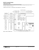
4.0 Jumper Setting
JP12 - Configures the Satellite Board (see Figure 2)
• Jumper across JP12, pins 1 and 2, configures the Satellite board for general purpose inputs and outputs.
• NO jumper across JP12 configures the Satellite board for second door control with additional inputs and outputs.
When the Satellite board is configured for second door control, the primary door must be connected to the "A" reader
(TB-5 on the PXL-500/PXL-510 controller board) and the secondary door must be connected to the "B" reader (TB-6
on the controller board).
Figure 2: Satellite Board Jumper Configuration (JP12)