
Manual
Technical Reference Manual – PXL-250 and SB-293 Keri Systems, Inc.
Page 98 P/N: 01836-004 Revision 5.5
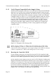
12.1 Communication LEDs
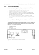
To help monitor controller/modem communication and to help troubleshoot modem
communication issues, a set of LEDs have been added to the upper-right corner of the
controller board (see Figure 9-1 on page 39 and Figure 12-1).
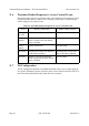
These LEDs flicker, corresponding to the state of the following lines.
• TXD – Transmit Data
• RXD – Receive Data
• DTR – Data Terminal Ready
• CTS – Clear To Send
By noting the operation being performed by the controller and monitoring the LED
states, you are able to determine if data transmission between modem and controller is
being performed.
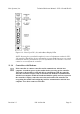
12.2 Power LEDs
Two LEDs are used to monitor the status of the power being supplied to the controller.
• Fuse LED
• Power/Voltage LED
12.2.1 Fuse LED
The Fuse LED (at the left side of the controller) is attached to a power monitoring
circuit protecting the 12 VDC power connection. The fuse circuit monitors power
polarity and power quality. This is a thermal fuse; if there is a power problem, the fuse
overheats and opens, removing power from the controller, protecting it from damage.
After a period of time the fuse cools off, reconnecting the power circuit. In standard
operation, the Fuse LED is off.
• If the LED is red, the fuse is open because the power and ground lines are
reversed. Turn controller power off and verify the polarity of the power coming to
the controller.
• If the LED is green, the controller’s fuse has opened because there is a power
problem, protecting the controller. This controller should be serviced as soon as
possible.