
Manual

Technical Reference Manual – PXL-250 and SB-293 Keri Systems, Inc.
Page 66 P/N: 01836-004 Revision 5.5
9.10.3.1 Modem/DB-25M to PC/DB-9F Cable Wiring
This is the wiring information for a cable that must be purchased or made by the
installer.
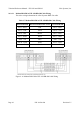
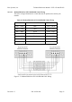
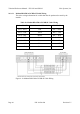
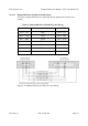
Figure 9-19: Modem/DB-25M to PC/DB-9F Cable Wiring
Table 19: Modem/DB-25M to PC/DB-9F Cable Wiring
Modem DB-25M RS-232 Standard Wire Color PC DB-9F
Pin 2 – RxD Red Pin 3 – RxD
Pin 3 – TxD Green Pin 2 – TxD
Pin 4 – RTS Brown Pin 7 – RTS
Pin 7 – GND Black Pin 5 – GND
Pin 8 – CD Blue Pin 1 – CD
Pin 20 – DTR White Pin 4 – DTR
Connector Body Shield Connector Body