
Manual

Keri Systems, Inc. Technical Reference Manual – PXL-250 and SB-293
Revision 5.5 P/N: 01836-004 Page 49
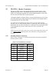
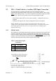
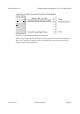
Figure 9-8: Door Status Switch Input Connections
NOTE: If a ground lead from the Request To Exit input has already been installed on
TB-4, pin 2, loosen the terminal connector and insert the door status ground lead
beside the RTE input ground lead.