
Manual

Technical Reference Manual – PXL-250 and SB-293 Keri Systems, Inc.
Page 46 P/N: 01836-004 Revision 5.5
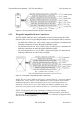
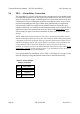
9.3.2 Auxiliary RTE A-Door
The normal state of the auxiliary RTE A-door input is an open circuit that will be
closed when an input is generated. No voltage is applied at this input; the circuit will
change state (open to closed) to indicate an input event. Refer to the Auxiliary Request
to Exit section starting on page 33 for more information on auxiliary RTE. Refer to
Table 8 and Figure 9-6 and make the following connections to attach an auxiliary RTE
A-door input.
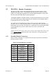
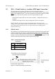
Figure 9-6: Auxiliary RTE A-Door Input Connections
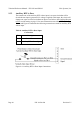
Table 8: Auxiliary RTE A-Door Input
Connections
TB-4 Description
Pin 5 Ground/Common
Pin 6 Auxiliary RTE A-Door Signal