
Manual

Keri Systems, Inc. Technical Reference Manual – PXL-250 and SB-293
Revision 5.5 P/N: 01836-004 Page 43
NOTE: All Keri Systems proximity readers can use between 5 and 12 VDC power
while most Wiegand compatible readers use 5 VDC power. Check your reader's
requirements and verify jumper JP4 is set correctly per the Jumper Settings
instructions on page 28. Early revisions of the surface mount PXL-250W mislabeled
the JP4 jumper as JP5. All instructions for the JP4 jumper apply to the jumper
labeled as JP5 (see Figure 9-1 on page 39 for the location of the jumper).
a. Refer to the Wiegand compatible reader’s documentation
for the color of this wire.
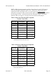
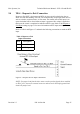
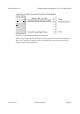
Table 4: Single-Line LED Wiegand Compatible
Reader Connections
TB-5/TB-6 Description Wire Color
Pin 1 Data 0 GREEN
Pin 2 Beeper
refer to reader
a
a. Refer to the Wiegand compatible reader’s
documentation for the color of this wire.
Pin 3 Reader Power RED
Pin 4 Reader Ground BLACK
Pin 5 n/a n/a
Pin 6 Single LED Line
refer to reader
a
Pin 7 Data 1 WHITE
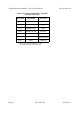
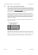
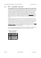
Table 5: Dual-Line LED Wiegand Compatible
Reader Connections
TB-5/TB-6 Description Wire Color
Pin 1 Data 0 GREEN
Pin 2 Beeper
refer to reader
a
Pin 3 Reader Power RED
Pin 4 Reader Ground BLACK
Pin 5 Green LED
refer to reader
a
Pin 6 Red LED
refer to reader
a
Pin 7 Data 1 WHITE