
Manual

Keri Systems, Inc. Technical Reference Manual – PXL-250 and SB-293
Revision 5.5 P/N: 01836-004 Page 41
9.2 TB-5/TB-6 – Reader Connection
The inputs on TB-5 accept wiring from Keri Systems proximity readers or from
Wiegand compatible devices. The standard PXL-250 uses Keri Systems proximity
readers. To use Wiegand compatible devices the Wiegand compatible version of the
PXL-250, the PXL-250W, must have been purchased.
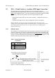
A Wiegand compatible controller will have circuitry installed in the lower left corner
of the PCB, allowing the voltage supplied by the controller to the Wiegand reader to
be changed between 5 VDC and 12 VDC.
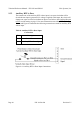
Two readers may be installed for one door to allow for access control in both
directions. The "A" reader, allowing entrance, is connected to TB-5 on the PXL-250
motherboard. The "B" reader, allowing exit, is connected to TB-6 on the motherboard.
If your application uses just one reader, connect it to TB-5 on the PXL-250
motherboard.
NOTE: If you are connecting readers for an elevator control application, please refer
to the Elevator Control Application Note (P/N 01878-001) in the appendix of this
document.
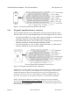
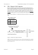
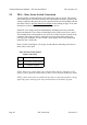
9.2.1 Proximity Reader Connection
Refer to Table 3 and Figure 9-3 and make the following connections to attach Keri
Systems proximity readers.
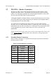
Table 3: Proximity Reader Connections
TB-5/TB-6 Description Wire Color
Pin 1 Antenna BLUE
Pin 2 Beeper GREEN
Pin 3 Reader Power RED
Pin 4 Reader Ground BLACK
Pin 5 Green LED BROWN
Pin 6 Red LED WHITE
Pin 7 NO CONNECTION n/a