
User Manual

Wiegand Elevator Control Panel
2305 Bering Drive 01942-001 Rev. D
San Jose, CA 95131 USA
(800) 260-5265 (408) 435-8400 FAX (408) 577-1792
Web: www.kerisys.com E-mail: sales@kerisys.com Page 21 of 24
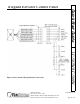
LC-502W/LC-508WQuick Start Guide
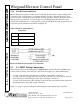
5.4.2 LC-508W/LC-508W Combination
Perform the following wiring instructions to accommodate an elevator application using up to four
LC-508W panels (up to 32 floors).
1. Make a complete set of connections to the first LC-508W panel. Refer to Section 5.3 on page 16
for all connections to the LC-508W.
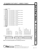
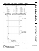
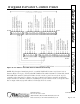
2. Daisy-chain the Data0, Ground, and Data1 reader connections from W-TB-B of the additional
LC-508W panel to W-TB-C of the previous LC-508W panel. Make the connections per the
information in Table 9 and Figure 14 on page 22.
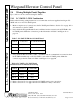
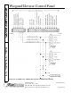
3. Daisy-chain the TxRx+, TxRx-, and Shield Network Communication connections from W-TB-
B of the additional LC-508W panel to W-TB-C of the previous LC-508W panel. Make the
connections per the information in Table 10 and Figure 15 on page 23.
4. The floor/relay connections for the additional LC-508W are made according to the floor/panel
association. Refer to Section 5.3 on page 16 for all floor/relay connections to the LC-508W.
Power connections are made per the instructions in Section 5.2.4 on page 16.
Table 9: LC-508W to LC-508W Panel Wiring Connections
W-TB-B
W-TB-B of Additional
Panel
W-TB-C of First/Previous
Panel
W-TB-C
Pin 1 Reader Ground (OUT) Reader Ground (IN) Pin 13
Pin 2 Data0 (OUT) Data0 (IN) Pin 16
Pin 3 Data1 (OUT) Data1 (IN) Pin 10
Table 10: LC-508W to LC-508W Panel Network Communication Wiring
W-TB-B
W-TB-B of Additional
Panel
W-TB-C of First/Previous
Panel
W-TB-C
Pin 4 TxRx - (OUT) TxRx - (IN) Pin 1
Pin 5 TxRx + (OUT) TxRx + (IN) Pin 2
Pin 6 Shield (OUT) Shield (IN) Pin 3