
Manual

Proximity Elevator Control Panel
2305 Bering Drive 01941-001 Rev. B
San Jose, CA 95131 USA
(800) 260-5265 (408) 435-8400 FAX (408) 577-1792
Web: www.kerisys.com E-mail: sales@kerisys.com Page 5 of 22
LC-502P/LC-508PQuick Start Guide
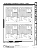
4.0 Controller Installation
Sections 4.1 and 4.2 are quick lists of things to do and to not do when installing LC-502P and LC-
508P panels.
4.1 Do
• Plan ahead to meet power and telephone requirements for your system (1 phone line for the host
computer and one for each master LC-500P controller in each network).
• Mount controllers in environmentally suitable areas – they require protection from weather and
from temperature/humidity extremes.
• Mount the controller at least 3 feet away from the controller's power supply to prevent EMI
radiated from the power supply from affecting the controller.
• Use isolation relays where needed.
• Use the enclosure as a mounting template to mark drilling holes for permanent mounting.
• Consider mounting requirements - central versus distributed.
- Central mounting places all controllers in one location, running lengths of cables out to each
door to support readers, inputs and outputs.
- Distributed mounting places each controller near the door it supports running short lengths
of cable out to each door, but running a long network communication cable.
• Note the locations of the knockouts in the enclosures and remove the appropriate knockout for
the easiest cable routing into the controller.
• Route all controllers in a network in a single, continuous daisy-chain.
• Route cables in accessible areas for ease of maintenance.
• Connect all controllers to a quality earth ground.
• Add transient suppression across electric devices attached to a controller output.
• Verify the controller's supply voltage is 12 VDC – long power line runs cause a drop in voltage
at the end of the run.
• Verify proper operation of the host computer's COM port.