
User Manual

Wiegand Elevator Control Panel
1530 Old Oakland Road, Suite 100 01879-002 Rev. C
San Jose, CA 95112 USA
(800) 260-5265 (408) 451-2520 FAX (408) 441-0309
Web: http://www.kerisys.com E-mail: sales@kerisys.com Page 18 of 24
Quick Start GuideLC-202W/LC-208W
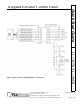
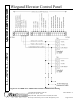
5.4 Wiring Multiple Panels Together
Up to 16 floors can be controlled using a combination of LC-202Ws and LC-208Ws; the first eight
floors must be controlled by an LC-208W. Any additional panel combinations of LC-208Ws and
LC-202Ws can then be used to reach the desired total.
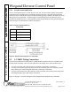
5.4.1 LC-208W/LC-202W Combination
Perform the following wiring instructions to accommodate an elevator application using an LC-
208W and one or more LC-202W panels.
1. Make a complete set of connections to the LC-208W panel. Refer to Section 5.3 on page 16 for
all connections to the LC-208W.
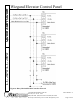
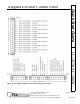
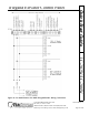
2. Daisy-chain the Wiegand Data0, Ground, and Data1 reader connections from W-TB-B to the
LC-202W panels. Make the connections per the information in Table 7 and Figure 11 on
page 19.
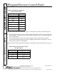
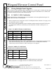
3. Daisy-chain the RS-485 TxRx+, TxRx-, and Shield network communication connections from
the W-TB-B terminal strip on the LC-208W to each of the LC-202W panels. Make the
connections per the information in Table 8 and Figure 12 on page 20.
4. Refer to Section 5.2.4 on page 16 for the LC-202W panel power connections.
5. Refer to Section 5.2.1 on page 10 for the LC-202W floor relay connections.
Table 7: LC-208W W-TB-B to LC-202W Panel
W-TB-B Connection LC-202W TB-5/TB-6
Pin 1 Reader Common Pin 1
Pin 2 Data0 Pin 4
Pin 3 Data1 Pin 7
Table 8: LC-208W to LC-202W Panel
RS-485 Network Communication Wiring
W-TB-B Connection LC-202W TB-1
Pin 4 TxRx- Pin 1
Pin 5 TxRx+ Pin 2
Pin 6 Shield Pin 3