
User Manual


LAN-520 AESP
Installation Guide
Page 3 of 13 P/N: 01519-001 Rev. B
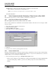
3.0 Installing the LAN-520 AESP on an Entraguard Unit
Support for the LAN unit on Entraguard begin with PCB 23217-001 Rev. E. Earlier units cannot support a LAN unit.
1. Power down the Entraguard master controller.
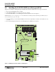
2. On the Entraguard PCB, remove jumpers from J11, J19, and J20.
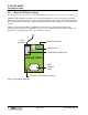
3. Insert the LAN-520X into J7 on the Entraguard. Orient the LAN unit as shown in Figure 2.
NOTE: Mounting screws are supplied to secure the LAN-520X to the Entraguard unit. The Entraguard PCB will have to
be removed from its enclosure to do this.
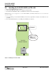
4. Connect the RJ-45 port on the LAN-520 AESP to the network via a patch cable or directly to the host PC via a cross-
over cable.
5. Power up the Entraguard unit (if this is a new Entraguard panel, a RAM reset is required).
Figure 3: Installing the LAN-520 AESP on an Entraguard
Alarm
Relay
Lock
Relay
GP
Output
Relay 2
GP
Output
Relay 1
6 5 4 3 2 1 6 5 4 3 2 1 6 5 4 3 2 1
3
2
1
6 5 4 3 2 1
1 2 3
2 1
485
U18
U2
Battery
D20 D18
D30
D29
D25
D32
SW1
R75
J3
J1
J6
J8
Internal
Modem
J11
J16 - Postal Lock Connection
JP1
JP2
J19J20
U5
J9
TB15
TB1
TB3TB4 TB10
TB12
Modem Module
LAN
Communication
Jumpers
J7
LAN-520
Connector
RxD
DTR
TxD
D41
LAN-520
AESP
NOTE: These jumpers MUST
be removed or connection will fail.
NETWORK
Mounting Stando