
Manual
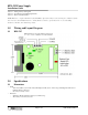
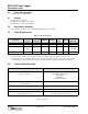
Table Of Contents
KPS-525 Power Supply
Installation Guide
Page 2 of 2 P/N: 01510-001 Rev. A
2.2 Power Requirements
• 24 VAC 50 VA Class 2 Transformer
2.3 Output
• 13.8 VDC @ 2.5 A (typical)
• 13.8 VDC @ .50 A (battery float charge)
• 14.2 VDC @ 2.0 A (DC output to NXT)
2.4 Operating Conditions
• 32°F to 150°F (0°C to 60°C) – 0% to 90% Relative Humidity, non-condensing
2.5 Cable Requirements
3.0 Contact Keri Systems
End of document.
Table 1: Cable Requirements
Connection
Total Run
Length
# of
Conductors
Shielded Stranded
Twisted
-Pair
AWG
a
a. Heavier gauges then those listed are always acceptable.
Belden
Equivalent
AC power in 10 feet 2 N Y N 18 8442
ground shortest
path
b
b. Use the shortest possible path from earth ground point to PCB. Connect the earth ground only to the
designated pin on the terminal block. This is important as all transient protection for the unit is made through
this earth ground connection. For unit protection, the earth ground connection should always be made first.
1 N N n/a 18 no specific
requirement
DC power out 10 feet 2 N Y N 18 8442
Keri USA Keri UK, Ireland, Europe
2305 Bering Drive
San Jose, CA 95131
Unit 17
Park Farm Industrial Estate
Ermine Street
Buntingford
Herts SG9 9AZ UK
Telephone: (800) 260-5265
(408) 435-8400
Telephone: + 44 (0) 870 444 7234
Fax: (408) 435-7163 Fax:+ 44 (0) 1763 274 106
Web: www.kerisys.com Web:www.kerisystems.co.uk
E-mail: sales@kerisys.com
techsupport@kerisys.com
E-mail:sales@kerisystems.co.uk
tech-support@kerisystems.co.uk