
User guide

Doors32™ Elevator Control
2305 Bering Drive 018
78-001 Rev. E
San J
ose, CA 95131 USA
(800) 260-5265 (408) 435-8400 FAX (408) 577-1792
Web:
www.kerisys.com E-mail: sales@kerisys.com Page 2 of 4
Application NoteDoors32™
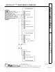
2.0 Wiring an Elevator Control System
For elevator control there are four reader to PXL-250 controller wiring connections that must be
made. Figure 1 provides a wiring diagram of an elevator control system.
1. The reader antenna line must be daisy-chained to all controller antenna inputs (Pin 1 of TB-5 or
TB-6 on the controllers).
2. The reader ground line must be daisy-chained to all controller antenna grounds to provide a
standard ground reference for all controllers (Pin 4 of TB-5 or TB-6 on the controllers).
3. The reader shield line must be connected to the A-door controller antenna ground at the master
controller (Pin 4 of TB-5 on the master controller).
4. The power line must be connected to the master controller only (Pin 3 of TB-5 on the master
controller).