
Installation Guide User guide

Keri Systems, Inc.
3
01956-001 Rev. A
www.kerisys.com
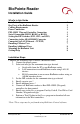
Cabling Requirements
BioPointe RS485: Belden 9501, 24 AWG, twisted pair, shielded.
BioPointe to PXL: Belden 3124A, one pair 18 AWG (power); one pair
22 AWG (data), shielded.
Power Connection
The BioPointe reader requires +12 to 24 VDC @ 500mA (~5w) at the reader.
If the power supply is located more than 100 feet from the reader, the wire
gauge you use must provide adequate power at the reader.
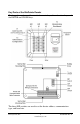
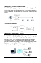
PXL-500W Wiegand Controller Connection
The Wiegand output from a BioPointe reader to a Keri Wiegand controller is
connected as follows:
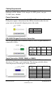
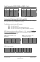
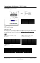
Serial Connection (RS232, RS485, or RS422)
A DB-9F (female) connector is required to connect the BioPointe reader
directly to a PC using a serial connection. The drawings and tables below
show the pin-outs for each type of serial connection.
Pin Description
1 GND
2 12 to 24 VDC
Wiegand
Line
W0 GND W1
BioPointe
Output
Pin 9 Pin 10 Pin 11
PXL-500W
TB5/TB6
Pin 1 Pin 4 Pin 7
BioPointe
Pin
RS-232 DB-9F Pin
3- -
4- -
5GND5
6Rx3
7Tx2
8- -
RS422 and RS485 pinouts are on the next page.