
Instruction Manual

Alarm Relay Board
Installation Guide
Page 2 of 3 P/N: 01513-001 Rev. A
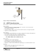
Figure 2: Tamper Switch Installation
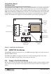
3.0 ARB Wiring Instructions
Refer to Figure 1 on page 1 for all instructions in this Section.
Tamper Switches
• provides the input signal for enclosure tamper events – enclosure cover forced open and/or
enclosure removed from its mounting location
• uses normally-open switches
• connection is made to either or both J3 and J5 (the switch connections are designed in parallel)
• requires two-conductor, AWG 22 wire
Bypass Jumpers
• used if a tamper switch is NOT used in one of the two switch positions (single-switch application)
• factory default is jumpers ON (bypasses both Tamper Switches)
• remove the corresponding jumper when a tamper switch is installed
- remove Bypass Jumper 1 (J4) for switch position 1 (J3)
- remove Bypass Jumper 2 (J6) for switch position 2 (J5)
Relay Contacts
• completes the circuit for alarm annunciation
• relay changes state as a tamper switch changes state
• Keri does NOT provide the alarm annunciation device
• requires two- or three-conductor, AWG 22 wire depending upon your alarm annunciation device
Unit Power
• requires 12 VDC, can be tapped off of the controller’s power
• requires two-conductor, AWG 22 wire
Enclosure
Wall
Tamper
Switch
Switch
Plunger
Switch
Connection
Wires