
Instruction Manual

34
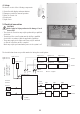
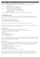
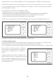
The following diagram shows the electrical connections on the output terminals of the light control:
1) Terminals for the supply cable from the distribution board
2) Terminals for cables to the lights of the four circuits
3) Terminals for the dimming cables to the lights of circuits 1 + 2
4) Cables to the four light sensors and four light buttons
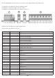
The connections are numbered as follows:
Terminal strip Terminal number Designation
X1 Mains supply feed
X2 1 Light circuit 1 power supply
2 Light circuit 2 power supply
3 Light circuit 3 power supply
4 Light circuit 4 power supply
X3 11 Dimming signal, light circuit 1 +
12 Dimming signal, light circuit 1 -
13 Dimming signal, light circuit 2 +
14 Dimming signal, light circuit 2 -
X4 21 Button 1 +
22 Button 1 -
24 Light sensor 1 +
25 Light sensor 1 -
31 Button 2 +
32 Button 2 -
34 Light sensor 2 +
35 Light sensor 2 -
41 Button 3 +
42 Button 3 -
44 Light sensor 3 +
45 Light sensor 3 -
51 Button 4 +
52 Button 4 -
54 Light sensor 4 +
1 2 3 4