
Instruction Manual

33
4. Setup
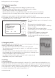
The device consists of the following components:
1) Controller with display and menu buttons
2) Emergency switch for manual operation
3) Relay for circuits 1–4
4) Power pack
5) Light sensor
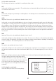
5. Electrical connection
CAUTION!
Risk of physical injury and material damage if used
incorrectly!
• The electrical connection may only be produced by a qualified
electrician.
• The wiring of the overall system must be laid by a qualified
electrician in accordance with the applicable regulations.
• The power supply to the light control may only be switched
on after all connection work is complete.
Work may only be performed when power to the system is off.
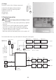
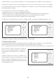
The sketch below shows one possible method of wiring the overall system:
5
Light sensor 2
Light sensor 1
Light sensor 3
Light sensor 4
...
Note installation
location of light sensor
Light sensor may be
indoors or outdoors
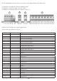
LED light control
Button 4
Button 3
Button 2
Button 1
3L-N-PE
max. 16 A
L-N-PE
max. 8 A
L-N-PE
max. 8 A
Light
Light
Circuit 4
Circuit 3
Circuit 1
Circuit 2
Light 1-10 V
Light 1-10 V
Note no. of lights!
1-10 V
L-N-PE
max. 16 A
Light
Light
Light
Light
Light 1-10 V
Light 1-10 V
Light 1-10 V
Light 1-10 V
123 4