
Operator Manual Firmware Ver.3.05 and higher Instruction Manual

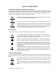
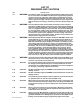
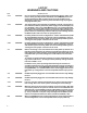
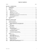
Table Of Contents
- SECTION 1 - INTRODUCTION
- SECTION 2 - INSTALLATION
- SECTION 3 - OPERATION
- SECTION 4 - CALIBRATION
- FIGURE 1-1. High Power BOP-GL Series Power Supply
- SECTION 1 - INTRODUCTION
- 1.1 Scope of Manual
- 1.2 General Description
- 1.3 Specifications
- TABLE 1-1. BOP-GL 1000 Watt Model Parameters
- TABLE 1-2. BOP General Specifications
- FIGURE 1-2. BOP-GL Power Supply, Outline Drawing
- 1.4 Remote Control
- 1.5 Features
- 1.5.1 Digital Calibration
- 1.5.2 voltage/current Protection
- 1.5.3 Waveforms
- 1.5.4 Saving and Recalling Settings
- 1.5.5 External Reference (Analog Control)
- 1.5.6 External Limits
- 1.5.7 User-defined Voltage/Current Maximum Values (Software Limits)
- 1.5.8 Parallel and Series Configurations
- 1.5.9 Energy Recuperation
- 1.6 Equipment Supplied
- TABLE 1-3. Equipment Supplied
- 1.7 Accessories
- 1.8 Safety
- TABLE 1-4. Safety Symbols
- FIGURE 1-3. BOP Output Characteristics
- TABLE 1-5. Accessories
- SECTION 2 - INSTALLATION
- 2.1 Unpacking and Inspection
- 2.2 Terminations and Controls
- FIGURE 2-1. BOP-GL Series Rear Panel
- TABLE 2-1. Rear Panel Connector Functions
- FIGURE 2-2. BOP-GL Top Cover Accessible Components
- TABLE 2-2. Power-Up Setup Switches
- TABLE 2-3. IEEE 1118 Connector Input/Output Pin Assignments
- TABLE 2-4. Trigger Port Pin Assignments
- TABLE 2-5. External Protection Connector Input/Output Pin Assignments
- TABLE 2-6. RS232C PORT Input/Output Pin Assignments
- TABLE 2-7. Parallel/Serial Control Out Port Pin Assignments
- TABLE 2-8. Parallel/Serial Control In Port Pin Assignments
- TABLE 2-9. Parallel/Serial Protect In Port Pin Assignments
- TABLE 2-10. Parallel/Serial Protect Out Port Pin Assignments
- TABLE 2-11. Analog I/O Port Input/Output Pin Assignments
- TABLE 2-12. IEEE 488 Port Input/Output Pin Assignments
- 2.3 Preliminary Operational Check
- 2.3.1 Preliminary Operational Check using Analog Control
- FIGURE 2-3. Factory Default Power-up Switch Settings
- 2.3.2 Preliminary Operational Check using Digital Control
- 2.4 Installation
- 2.4.1 Rack Mounting
- 2.4.2 Slide Installation
- 2.5 Wiring Instructions
- 2.5.1 Safety Grounding
- 2.5.2 Source Power Connections
- 2.5.3 D-C Output Grounding
- 2.5.3.1 Grounding Network Configuration
- 2.5.4 Power Supply/Load Interface
- 2.5.5 Load Connection - General
- 2.5.6 Load Connection Using Local Sensing
- 2.5.7 Load Connection Using Remote Sensing
- 2.6 Cooling
- 2.7 Setting up the unit
- 2.7.1 Power-up Settings
- FIGURE 2-4. Load Connections, Local Sensing
- FIGURE 2-5. Load Connections, Remote Sensing
- 2.7.2 Setup for Analog Control
- 2.7.3 Setup for Digital Control via GPIB
- 2.7.4 Setup for Digital Control via RS 232C
- FIGURE 2-6. Connections for Analog Control and Monitoring of BOP-GL Power Supply.
- 2.8 Multiple Unit Configurations
- 2.8.1 Multiple Unit Connections
- FIGURE 2-7. Parallel Configuration, Local Sensing, Typical
- FIGURE 2-8. Parallel Configuration, Remote Sensing, Typical
- FIGURE 2-9. Series Configuration, Local Sensing, Typical
- FIGURE 2-10. Series Configuration, Remote Sensing, Typical
- 2.8.2 Multiple Unit Source Power
- 2.8.3 Multiple Unit Protection
- FIGURE 2-11. Typical Master/Slave Protection Interconnections
- 2.8.4 Operating Instructions for Multiple Unit Combinations
- 2.8.5 Restoring a Unit to Standalone Operation
- SECTION 3 - OPERATION
- 3.1 General
- 3.2 Power-up Settings
- 3.2.1 Changing the Default Power-up Settings
- 3.3 Power Supply Basics
- 3.3.1 Controls and Indicators
- FIGURE 3-1. BOP-GL Series Front Panel
- TABLE 3-1. Front Panel Controls and Indicators
- 3.3.2 Turning the Power Supply On
- 3.3.2.1 Reset Power-up
- 3.3.2.2 Normal Power-up
- 3.3.3 Voltage and Current Parameters
- 3.3.4 Voltage/Current Protect Limits (Limit Channel Software Limits)
- 3.3.4.1 Hidden Voltage and Current Protect Limits
- TABLE 3-2. Voltage and Current Parameter Definitions
- 3.3.5 Maximum Accepted Voltage or Current (Main Channel Software Limits)
- 3.3.6 Maximum/Minimum Protection Limits (Software-controlled)
- 3.3.7 Determining How the Unit responds when Output is OFF (Load Type)
- TABLE 3-3. Power Supply Behavior when Output is set to OFF
- 3.3.8 External Limits
- 3.3.9 Enabling/Disabling DC Output Power
- 3.3.9.1 Remote Shutdown
- FIGURE 3-2. Remote Shutdown Using External Power, Standalone or Multiple units
- FIGURE 3-3. Remote Shutdown Using Internal Power, Standalone Units
- FIGURE 3-4. Remote Shutdown Using Internal Power, Multiple Units,
- 3.3.9.2 Remote On-OFF Using Trigger Port Pin 2
- 3.3.9.3 Remote On-OFF Using Trigger port (off) and Digital Command (on)
- 3.3.9.4 Remote On-OFF Using Digital Commands
- FIGURE 3-5. Remote On-Off, Standalone or Multiple Units
- 3.3.10 Setting Main Channel Mode (Voltage or Current)
- 3.3.11 Protection Limits
- 3.4 Analog Remote Mode Programming
- 3.4.1 Controlling the Output Using the BOP as a Power Amplifier
- 3.4.1.1 Fixed Gain using External Reference Control
- 3.4.1.2 Variable Gain Using External Reference Level
- 3.4.2 External Protection Limits
- 3.4.2.1 Using Lesser of Digital vs. Analog (External) limits
- 3.4.3 Monitoring Output Current Using an analog signal
- 3.5 Digital Control
- 3.5.1 Password Protection
- 3.5.2 Setting Operating Mode (Voltage or Current)
- 3.5.3 Programming Voltage or Current and Associated Protect Limits
- 3.5.4 Programming Associated Protect Limits
- 3.5.4.1 When Operating in Voltage Mode
- 3.5.4.2 When Operating in Current Mode
- 3.5.5 Programming Techniques to Optimize performance
- 3.5.5.1 Programming Voltage/Current Limit and Current/Voltage Limit
- 3.5.5.2 Making Sure the Previous Command is Complete
- 3.5.6 Storing/Recalling Power Supply Output Settings
- FIGURE 3-6. Programming Example to Verify Previous Command has Completed
- 3.5.7 Waveform Generation
- 3.5.7.1 Waveform Overview
- 3.5.7.2 Understanding How Waveforms Are Generated
- TABLE 3-4. Sine, Triangle and Ramp Waveform Frequency vs. Points
- TABLE 3-5. Square Waveform Frequency vs. Points
- 3.5.7.3 Waveform Specifications
- FIGURE 3-7. Sample Waveform
- 3.5.7.4 Executing a Waveform
- TABLE 3-6. Waveform Segment Details
- 3.5.7.5 Using Segments to Build a Waveform
- 3.5.8 Reset
- TABLE 3-7. Operation of #RST Command
- 3.5.9 Error Message Explanations
- 3.6 Programming Using Digital Control
- 3.6.1 BIT 4882 Compatibility.
- 3.6.2 BIT 4886 Compatibility
- 3.6.3 IEEE 488 (GPIB) Bus Protocol
- TABLE 3-8. IEEE 488 (GPIB) Bus Interface Functions
- TABLE 3-9. IEEE 488 (GPIB) Bus Command Mode Messages
- TABLE 3-10. IEEE 488 (GPIB) Bus Data Mode Messages
- 3.6.3.1 GPIB Port Setup
- 3.6.3.1.1 Changing the GPIB Address
- 3.6.3.1.2 Configure Device Clear (DCL) Control
- 3.6.3.1.3 Determining Whether *RST Command sets the Output Off or On
- 3.6.4 RS232-C Operation
- 3.6.4.1 Serial Interface
- 3.6.4.2 RS 232 Implementation
- FIGURE 3-8. RS 232 Implementation
- 3.6.4.2.1 XON XOFF Method
- 3.6.4.2.2 Echo Mode
- 3.6.4.2.3 Prompt Method
- 3.6.4.3 RS 232 Serial Port Setup
- 3.6.4.3.1 Select Baud Rate
- 3.6.4.3.2 Configure Echo Protocol
- 3.6.4.3.3 Configure XON/XOFF Protocol
- 3.6.4.3.4 Configure Prompt Mode
- 3.6.5 BOP VISA Instrument driver
- 3.7 SCPI Programming
- 3.7.1 SCPI Messages
- 3.7.2 Common Commands/Queries
- 3.7.3 SCPI Subsystem Command/Query Structure
- 3.7.3.1 ABORt Subsystem
- 3.7.3.2 INITiate Subsystem
- 3.7.3.3 LIST Subsystem
- 3.7.3.3.1 Required LIST Commands
- 3.7.3.3.2 Other Required Commands
- 3.7.3.3.3 Other Useful Commands
- 3.7.3.3.4 Optional Commands
- 3.7.3.4 MEASure Subsystem
- 3.7.3.5 OUTPut Subsystem
- 3.7.3.6 MEMory Subsystem
- FIGURE 3-9. Tree Diagram of SCPI Commands Used with BOP Power Supply
- 3.7.3.7 STATus Subsystem
- 3.7.3.8 TRIGger subsystem
- 3.7.3.9 [SOURce:]VOLTage and [SOURce:]CURRent Subsystems
- 3.7.3.10 CALibrate Subsystem
- 3.7.3.11 System Subsystem
- 3.7.3.11.1 Forgotten Passwords
- 3.7.4 Program Message Structure
- 3.7.4.1 Keyword
- TABLE 3-11. Rules Governing Shortform Keywords
- 3.7.4.2 Keyword Separator
- 3.7.4.3 Query Indicator
- 3.7.4.4 Data
- 3.7.4.5 Data Separator
- FIGURE 3-10. Message Structure
- 3.7.4.6 Message Unit Separator
- 3.7.4.7 Root Specifier
- 3.7.4.8 Message Terminator
- 3.7.5 Understanding The Command Structure
- 3.7.6 Program Message Syntax Summary
- 3.7.7 Status Reporting
- 3.7.7.1 Status Reporting Structure
- FIGURE 3-11. Status Reporting Structure
- 3.7.7.2 Operational Status Register
- 3.7.7.3 QUEStionable Status Register
- 3.7.8 SCPI Program Examples
- FIGURE 3-12. Typical Example Of BOP Power Supply Program Using SCPI Commands
- 3.8 Operator Troubleshooting
- SECTION 4 - CALIBRATION
- 4.1 General
- TABLE 4-1. Calibration Summary
- 4.2 Test Equipment Requirements
- TABLE 4-2. Suggested Sense Resistors
- TABLE 4-3. Voltage Calibration Measurements and Tolerances
- 4.3 Calibration using Remote SCPI commands via GPIB or RS 232 Interface
- TABLE 4-4. Current Calibration Measurements and Tolerances
- 4.3.1 Calibration Procedure using SCPI Commands
- FIGURE 4-1. Calibration Setup in Voltage Mode
- FIGURE 4-2. Calibration Setup in Current Mode
- 4.3.2 Calibration of Series- or Parallel-Connected Units
- 4.4 Calibration Storage
- TABLE 4-5. Calibration Storage
- APPENDIX A - SCPI COMMON COMMAND/QUERY DEFINITIONS
- A.1 Introduction
- TABLE A-1. IEEE 488.2 Command/query Index
- A.2 *CLS — Clear Status Command
- A.3 *ESE — Standard Event Status Enable Command
- TABLE A-2. Standard Event Status Enable Register and Standard Event Status Register Bits
- A.4 *ESE? — Standard Event Status Enable Query
- A.5 *ESR? — Event Status Register Query
- A.6 *IDN? — Identification Query
- A.7 *OPC — Operation Complete Command
- A.8 *OPC? — Operation Complete Query
- FIGURE A-1. GPIB Commands
- A.9 *OPT? — Options Query
- A.10 *RCL — Recall Command
- A.11 *RST — Reset Command
- A.12 *SAV — Save Command
- A.13 *SRE — Service Request Enable Command
- TABLE A-3. Service Request Enable and Status Byte Register Bits
- A.14 *SRE? — Service Request Enable Query
- A.15 *STB? — Status Byte Register Query
- A.16 *TRG — Trigger Command
- A.17 *TST? — Self Test Query
- TABLE A-4. Built-in test Error Codes
- A.18 *WAI — Wait-To-Continue Command
- APPENDIX B - SCPI COMMAND/QUERY DEFINITIONS
- B.1 Introduction
- TABLE B-1. SCPI Subsystem Command/query Index
- B.2 Numerical Values
- B.3 ABORt Command
- B.4 CAL Commands and Queries
- B.5 INITiate[:IMMediate] Command
- FIGURE B-1. Programming the Output
- B.6 INITiate:CONTinuous Command
- B.7 INITiate:CONTinuous Query
- B.8 MEASure[:SCALar]:CURRent[:DC]? Query
- B.9 MEASure[:SCALar]:MODE[:DC] Command
- B.10 MEASure[:SCALar]:VOLTage[:DC]? Query
- B.11 MEASure[:SCALar]:TRANsient[:DC]? QUERY
- B.12 MEMory:UPDate Command
- FIGURE B-2. Using List Commands to measure sample at End of Pulse
- FIGURE B-3. Using List Commands to measure sample at Start of Pulse
- B.13 OUTPut[:STATe] Command
- B.14 OUTPut[:STATe] Query
- B.15 OUTPut:CONTrol Command
- B.16 OUTPut:CONT? Query
- B.17 OUTPut:MODE Command
- B.18 OUTPut:MODE? Query
- B.19 [SOURce:]CURRent[:LEVel][:IMMediate][:AMPlitude] Command
- B.20 [SOURce:]CURRent[:LEVel][:IMMediate][:AMPlitude] Query
- B.21 [SOURce:]CURRent[:LEVel]:LIMIT[:BOTH] Command
- FIGURE B-4. Setting Limits
- B.22 [SOURce:]CURRent[:LEVel]:LIMIT[:BOTH]? Query
- B.23 [SOURce:]CURRent[:LEVel]:LIMIT:NEG Command
- B.24 [SOURce:]CURRent[:LEVel]:LIMIT:NEG? Query
- B.25 [SOURce:]CURRent[:LEVel]:LIMIT:POS Command
- B.26 [SOURce:]CURRent[:LEVel]:LIMIT:POS? Query
- B.27 [SOURce:]CURRent:MODE Command
- B.28 [SOURce:]CURRent:MODe? Query
- B.29 [SOURce:]CURRent[:LEVel]:PROTect[:BOTH] Command
- B.30 [SOURce:]CURRent[:LEVel]:PROTect[:BOTH] Query
- B.31 [SOURce:]CURRent[:LEVel]:PROTect:MODE Command
- B.32 [SOURce:]CURRent[:LEVel]:PROTect:MODE? Query
- B.33 [SOURce:]CURRent[:LEVel]:PROTect:NeGative Command
- B.34 [SOURce:]CURRent[:LEVel]:PROTect:NeGative? Query
- B.35 [SOURce:]CURRent[:LEVel]:PROTect:POSitive Command
- B.36 [SOURce:]CURRent[:LEVel]:PROTect:POSitive? Query
- B.37 [SOURce:]CURRent[:LEVel]:PROTect:LIMit[:BOTH] Command
- B.38 [SOURce:]CURRent[:LEVel]:PROTect:LIMit[:BOTH]? Query
- B.39 [SOURce:]CURRent[:LEVel]:PROTect:LIMit:NeGative Command
- B.40 [SOURce:]CURRent[:LEVel]:PROTect:LIMit:NeGative? Query
- B.41 [SOURce:]CURRent[:LEVel]:PROTect:LIMit:POSitive Command
- B.42 [SOURce:]CURRent[:LEVel]:PROTect:LIMit:POSitive? Query
- B.43 [SOURce:]CURRent[:LEVel]:TRIGgered[:AMPlitude] Command
- B.44 [SOURce:]CURRent[:LEVel]:TRIGgered[:AMPlitude]? Query
- B.45 [SOURce:]FUNCtion:MODE Command
- B.46 [SOURce:]FUNCtion:MODE? Query
- B.47 [SOURce:]FUNCtion:MODE:TRIGger Command
- B.48 [SOURce:]FUNCtion:MODE:TRIGger? Query
- B.49 [SOURce:]LIST:CLEar Command
- B.50 [SOURce:]LIST:COUNt Command
- B.51 [SOURce:]LIST:COUNt? Query
- FIGURE B-5. Using LIST Commands and Queries
- B.52 [SOURce:]LIST:COUNt:SKIP Command
- B.53 [SOURce:]LIST:COUNt:SKIP? Query
- B.54 [SOURce:]LIST:CURRent Command
- TABLE B-2. List Data Table
- B.55 [SOURce:]LIST:CURRent? Query
- B.56 [SOURce:]LIST:CURR:APPLy Command
- B.57 [SOURce:]LIST:CURRent:APPLy:SWEep Command
- B.58 [SOURce:]LIST:CURRent:APPLy:SWEep? Query
- B.59 [SOURce:]LIST:CURRent:POINts? Query
- B.60 [SOURce:]LIST:DWELl Command
- B.61 [SOURce:]LIST:DWELl? Query
- B.62 [SOURce:]LIST:DWELl:POINts? Query
- B.63 [SOURce:]LIST:QUERy Command
- B.64 [SOURce:]LIST:QUERy? Query
- B.65 [SOURce:]LIST:REPeat Command
- B.66 [SOURce:]LIST:RESolution? Query
- B.67 [SOURce:]LIST:SAMPle:CURRent Command
- B.68 [SOURce:]LIST:SAMPle:VOLTage Command
- B.69 [SOURce:]LIST:SAMPle? Query
- B.70 [SOURce:]LIST:SET:SAMPle Command
- B.71 [SOURce:]LIST:SET:SAMPle? Query
- B.72 [SOURce:]LIST:SET:TRIGger Command
- B.73 [SOURce:]LIST:SET:TRIGger? QUERY
- B.74 [SOURce:]LIST:SET:WAIT Command
- B.75 [SOURce:]LIST:SET:WAIT? QUERY
- B.76 [SOURce:]LIST:TRIGger Command
- B.77 [SOURce:]LIST:VOLTage Command
- B.78 [SOURce:]LIST:VOLTage? Query
- FIGURE B-6. Using LIST Commands for Sawtooth and Triangle Waveforms
- FIGURE B-7. Using List:WAIT Commands to Control Generation of a Waveform Measured by Multiple External Devices using a Single External Pulse
- FIGURE B-8. Using List:WAIT Commands to allow an external device time to function while imposing a maximum wait time
- B.79 [SOURce:]LIST:VOLT:APPLy Command
- B.80 [SOURce:]LIST:VOLTage:APPLy:SWEep Command
- B.81 [SOURce:]LIST:VOLTage:APPLy:SWEep? Query
- B.82 [SOURce:]LIST:VOLTage:POINts? Query
- B.83 [SOURce:]LIST:WAIT:HIGH Command
- B.84 [SOURce:]LIST:WAIT:LEDGe Command
- B.85 [SOURce:]LIST:WAIT:LOW Command
- FIGURE B-9. Using List:WAIT Commands to Control Generation of a Waveform Measured by Multiple External Devices using the Low-Going leading Edge of an External Pulse
- B.86 [SOURce:]VOLTage[:LEVel][:IMMediate][:AMPlitude] Command
- B.87 [SOURce:]VOLTage[:LEVel][:IMMediate][:AMPlitude]? Query
- B.88 [SOURce:]VOLTage[:LEVel]:LIMit[:BOTH] Command
- B.89 [SOURce:]VOLTage[:LEVel]:LIMit[:BOTH]? Query
- B.90 [SOURce:]VOLTage[:LEVel]:LIMit:NEGative Command
- B.91 [SOURce:]VOLTage[:LEVel]:LIMit:NEGative? Query
- B.92 [SOURce:]VOLTage[:LEVel]:LIMit:posItive Command
- B.93 [SOURce:]VOLTage[:LEVel]:LIMit:posItive? Query
- B.94 [SOURce:]VOLTage:MODe Command
- B.95 [SOURce:]VOLTage:MODE? Query
- B.96 [SOURce:]VOLTage[:LEVel]:PROTect:BOTH Command
- FIGURE B-10. Using PROT:LIM:POS and PROT:LIM:POS Commands to Set Asymmetrical Limits
- B.97 [SOURce:]VOLTage[:LEVel]:PROTect[:BOTH]? Query
- B.98 [SOURce:]VOLTage[:LEVel]:PROTect:MODE Command
- B.99 [SOURce:]VOLTage[:LEVel]:PROTect:MODE? Query
- B.100 [SOURce:]VOLTage[:LEVel]:PROTect:NeGative Command
- B.101 [SOURce:]VOLTage[:LEVel]:PROTect:NeGative? Query
- B.102 [SOURce:]VOLTage[:LEVel]:PROTect:POSitive Command
- B.103 [SOURce:]VOLTage[:LEVel]:PROTect:POSitive? Query
- B.104 [SOURce:]VOLTage[:LEVel]:PROTect:LIMit:BOTH Command
- B.105 [SOURce:]VOLTage[:LEVel]:PROTect:LIMit[:BOTH]? Query
- B.106 [SOURce:]VOLTage[:LEVel]:PROTect:LIMit:NeGative Command
- B.107 [SOURce:]VOLTage[:LEVel]:PROTect:LIMit:NeGative? Query
- B.108 [SOURce:]VOLTage[:LEVel]:PROTect:LIMit:POSitive Command
- B.109 [SOURce:]VOLTage[:LEVel]:PROTect:LIMit:POSitive? Query
- B.110 [SOURce:]VOLTage[:LEVel]:TRIGgered[:AMPlitude] Command
- B.111 [SOURce:]VOLTage[:LEVel]:TRIGgered[:AMPlitude]? Query
- B.112 STATus:OPERation:CONDition? Query
- TABLE B-3. Operation Condition Register, Operation Enable Register, and Operation Event Register Bits
- B.113 STATus:OPERation:ENABle Command
- B.114 STATus:OPERation:ENABle? Query
- B.115 STATus:OPERation[:EVENt] Query
- B.116 STATus:PRESet Command
- B.117 STATus:QUEStionable[:EVENt]? Query
- TABLE B-4. Questionable Event Register, Questionable Condition Register and Questionable Condition Enable Register Bits
- B.118 STATus:QUEStionable:CONDition? Query
- B.119 STATus:QUEStionable:ENABle Command
- FIGURE B-11. Using Status Commands and Queries
- B.120 STATus:QUEStionable:ENABle? Query
- B.121 SYSTem:BEEP Command
- B.122 SYSTem:COMMunication:GPIB:ADDRess Command
- B.123 SYSTem:COMMunication:GPIB:ADDRess? Query
- B.124 SYSTem:COMMunication:SERial:BAUD Command
- B.125 SYSTem:COMMunication:SERial:BAUD? Query
- B.126 SYSTem:COMMunication:SERial:ECHO Command
- B.127 SYSTem:COMMunication:SERial:ECHO? Query
- B.128 SYSTem:COMMunication:SERial:PACE Command
- B.129 SYSTem:COMMunication:SERial:PACE? Query
- B.130 SYSTem:COMMunication:SERial:PROMpt CommanD
- B.131 SYSTem:COMMunication:SERial:PROMpt? Query
- B.132 SYSTem:ERRor? Query
- B.133 SYSTem:ERRor:CODE? Query
- B.134 SYSTem:ERRor:CODE:ALL? Query
- B.135 SYSTem:KEYBoard Command
- B.136 SYSTem:KEYBoard? Query
- B.137 SYSTem:PASSword:CENable Command
- B.138 SYSTem:PASSword:CDISable Command
- B.139 SYSTem:PASSword:NEW Command
- B.140 SYSTem:PASSword:STATe? Query
- B.141 SYSTem:REMote Command
- B.142 SYSTem:REMote? Query
- FIGURE B-12. Setting the Unit to Remote Mode via Serial (RS 232) Port
- B.143 SYSTem:SECurity:IMMediate Command
- B.144 SYSTem:SET Command
- B.145 SYSTem:SET? Query
- B.146 SYSTem:VERSion? Query
- FIGURE B-13. Using System Commands and Queries
- B.147 TRIGger:SOURce Command
- B.148 TRIGger:SOURce? Query
- TABLE B-5. Error Messages
LIST OF
WARNINGS AND CAUTIONS
BOP 1KW OPR 2/28/14 E
PAGE WARNING/CAUTION
3-8 WARNING: For inductive loads, and especially superconducting magnet type loads,
the inherent offset of the BOP in the OFF state may generate significant
current in the circuit. A properly rated switch in parallel with a resistor
must be connected between the power supply and the load. The switch
must be open and voltage and current measurements at the output must
read 0V, 0A before removing or installing connections between BOP and
load.
3-9
WARNING: For both inductive loads and constant-current-type active electronic
loads when the BOP output is set to OFF, a path is provided for absorbing
either the energy accumulated in the reactance of the load during the ON
state, or energy delivered by an electronic load. This prevents damage to
the load and power supply as well as providing safety for the user. How-
ever, In addition to the built-in safety features, constant-current-type ac-
tive electronic loads must be adjusted to zero and voltage and current
measurements at the output must read 0V, minimum current, before han-
dling the power supply-to-load connections.
3-9
WARNING: Accessing the BOP after the output is disabled in BATTERY mode is haz-
ardous because (1) high current arcing is possible and (2) either the ex-
ternal battery voltage, or the voltage (±Voltage Protection max) on the
BOP output terminals may be dangerous. Therefore, for battery and con-
stant-voltage-type active electronic loads it is recommended that two
properly rated external switches be installed for safety: one in series with
the battery, and one across the BOP output. After the unit is set to OFF,
first open the switch in series with the battery, then close the switch
across the BOP output to ensure safety before handling BOP connec-
tions. When connecting the battery, the switch across the output should
be opened after the connections are complete and then the switch in se-
ries with the battery should be closed. If the constant-voltage-type active
electronic load is adjusted to zero before handling the power supply-to-
load connections, only the switch across the BOP output is required.
4-8
WARNING: The sense resistor will be dissipating full rated current of the BOP. If it is
hot to the touch, the sense resistor value, power rating and/or cooling are
incorrect; refer to PAR. 4.3 and Table 4-2.
2-8 CAUTION: it is recommended that source power of external equipment connected to
the Analog Port be applied through an isolating transformer to avoid
ground loops or possible damage to the BOP due to incorrect equipment
a-c wiring (e.g., defeating of ground connection).
2-10 CAUTION: DO NOT repeatedly toggle the POWER circuit breaker/switch as this may
damage the unit.
2-11 CAUTION: DO NOT repeatedly toggle the POWER circuit breaker/switch as this may
damage the unit.
2-11 CAUTION: The rack must provide support at the rear (within 6 inches of the rear pan-
el). Optional slides can also be used (see PAR. 2.4.2).
2-12 CAUTION: When working with active loads, the voltage or current of the active load
must not exceed the maximum voltage or current rating of the BOP. Oth-
erwise the overvoltage or overcurrent protection will shut down the pow-
er supply.
2-14 CAUTION: Never connect the load to the sense terminals. Monitoring instruments
(e.g., DVM, etc.) are the only external equipment that may be safely con-
nected to the sense terminals.
2-14 CAUTION: Never connect the BOP OUTPUT terminal (or the load terminal tied to the
OUTPUT terminal) to earth-ground. Otherwise, if the controlling device is
grounded, the BOP can be damaged by the protection limit output current
flowing inside the BOP along the programming signal return path.