
Operator Manual Firmware Ver.3.05 and higher Instruction Manual
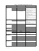
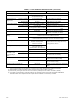
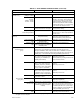
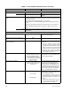
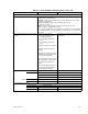
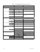
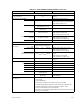
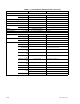
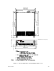
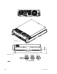
Table Of Contents
- SECTION 1 - INTRODUCTION
- SECTION 2 - INSTALLATION
- SECTION 3 - OPERATION
- SECTION 4 - CALIBRATION
- FIGURE 1-1. High Power BOP-GL Series Power Supply
- SECTION 1 - INTRODUCTION
- 1.1 Scope of Manual
- 1.2 General Description
- 1.3 Specifications
- TABLE 1-1. BOP-GL 1000 Watt Model Parameters
- TABLE 1-2. BOP General Specifications
- FIGURE 1-2. BOP-GL Power Supply, Outline Drawing
- 1.4 Remote Control
- 1.5 Features
- 1.5.1 Digital Calibration
- 1.5.2 voltage/current Protection
- 1.5.3 Waveforms
- 1.5.4 Saving and Recalling Settings
- 1.5.5 External Reference (Analog Control)
- 1.5.6 External Limits
- 1.5.7 User-defined Voltage/Current Maximum Values (Software Limits)
- 1.5.8 Parallel and Series Configurations
- 1.5.9 Energy Recuperation
- 1.6 Equipment Supplied
- TABLE 1-3. Equipment Supplied
- 1.7 Accessories
- 1.8 Safety
- TABLE 1-4. Safety Symbols
- FIGURE 1-3. BOP Output Characteristics
- TABLE 1-5. Accessories
- SECTION 2 - INSTALLATION
- 2.1 Unpacking and Inspection
- 2.2 Terminations and Controls
- FIGURE 2-1. BOP-GL Series Rear Panel
- TABLE 2-1. Rear Panel Connector Functions
- FIGURE 2-2. BOP-GL Top Cover Accessible Components
- TABLE 2-2. Power-Up Setup Switches
- TABLE 2-3. IEEE 1118 Connector Input/Output Pin Assignments
- TABLE 2-4. Trigger Port Pin Assignments
- TABLE 2-5. External Protection Connector Input/Output Pin Assignments
- TABLE 2-6. RS232C PORT Input/Output Pin Assignments
- TABLE 2-7. Parallel/Serial Control Out Port Pin Assignments
- TABLE 2-8. Parallel/Serial Control In Port Pin Assignments
- TABLE 2-9. Parallel/Serial Protect In Port Pin Assignments
- TABLE 2-10. Parallel/Serial Protect Out Port Pin Assignments
- TABLE 2-11. Analog I/O Port Input/Output Pin Assignments
- TABLE 2-12. IEEE 488 Port Input/Output Pin Assignments
- 2.3 Preliminary Operational Check
- 2.3.1 Preliminary Operational Check using Analog Control
- FIGURE 2-3. Factory Default Power-up Switch Settings
- 2.3.2 Preliminary Operational Check using Digital Control
- 2.4 Installation
- 2.4.1 Rack Mounting
- 2.4.2 Slide Installation
- 2.5 Wiring Instructions
- 2.5.1 Safety Grounding
- 2.5.2 Source Power Connections
- 2.5.3 D-C Output Grounding
- 2.5.3.1 Grounding Network Configuration
- 2.5.4 Power Supply/Load Interface
- 2.5.5 Load Connection - General
- 2.5.6 Load Connection Using Local Sensing
- 2.5.7 Load Connection Using Remote Sensing
- 2.6 Cooling
- 2.7 Setting up the unit
- 2.7.1 Power-up Settings
- FIGURE 2-4. Load Connections, Local Sensing
- FIGURE 2-5. Load Connections, Remote Sensing
- 2.7.2 Setup for Analog Control
- 2.7.3 Setup for Digital Control via GPIB
- 2.7.4 Setup for Digital Control via RS 232C
- FIGURE 2-6. Connections for Analog Control and Monitoring of BOP-GL Power Supply.
- 2.8 Multiple Unit Configurations
- 2.8.1 Multiple Unit Connections
- FIGURE 2-7. Parallel Configuration, Local Sensing, Typical
- FIGURE 2-8. Parallel Configuration, Remote Sensing, Typical
- FIGURE 2-9. Series Configuration, Local Sensing, Typical
- FIGURE 2-10. Series Configuration, Remote Sensing, Typical
- 2.8.2 Multiple Unit Source Power
- 2.8.3 Multiple Unit Protection
- FIGURE 2-11. Typical Master/Slave Protection Interconnections
- 2.8.4 Operating Instructions for Multiple Unit Combinations
- 2.8.5 Restoring a Unit to Standalone Operation
- SECTION 3 - OPERATION
- 3.1 General
- 3.2 Power-up Settings
- 3.2.1 Changing the Default Power-up Settings
- 3.3 Power Supply Basics
- 3.3.1 Controls and Indicators
- FIGURE 3-1. BOP-GL Series Front Panel
- TABLE 3-1. Front Panel Controls and Indicators
- 3.3.2 Turning the Power Supply On
- 3.3.2.1 Reset Power-up
- 3.3.2.2 Normal Power-up
- 3.3.3 Voltage and Current Parameters
- 3.3.4 Voltage/Current Protect Limits (Limit Channel Software Limits)
- 3.3.4.1 Hidden Voltage and Current Protect Limits
- TABLE 3-2. Voltage and Current Parameter Definitions
- 3.3.5 Maximum Accepted Voltage or Current (Main Channel Software Limits)
- 3.3.6 Maximum/Minimum Protection Limits (Software-controlled)
- 3.3.7 Determining How the Unit responds when Output is OFF (Load Type)
- TABLE 3-3. Power Supply Behavior when Output is set to OFF
- 3.3.8 External Limits
- 3.3.9 Enabling/Disabling DC Output Power
- 3.3.9.1 Remote Shutdown
- FIGURE 3-2. Remote Shutdown Using External Power, Standalone or Multiple units
- FIGURE 3-3. Remote Shutdown Using Internal Power, Standalone Units
- FIGURE 3-4. Remote Shutdown Using Internal Power, Multiple Units,
- 3.3.9.2 Remote On-OFF Using Trigger Port Pin 2
- 3.3.9.3 Remote On-OFF Using Trigger port (off) and Digital Command (on)
- 3.3.9.4 Remote On-OFF Using Digital Commands
- FIGURE 3-5. Remote On-Off, Standalone or Multiple Units
- 3.3.10 Setting Main Channel Mode (Voltage or Current)
- 3.3.11 Protection Limits
- 3.4 Analog Remote Mode Programming
- 3.4.1 Controlling the Output Using the BOP as a Power Amplifier
- 3.4.1.1 Fixed Gain using External Reference Control
- 3.4.1.2 Variable Gain Using External Reference Level
- 3.4.2 External Protection Limits
- 3.4.2.1 Using Lesser of Digital vs. Analog (External) limits
- 3.4.3 Monitoring Output Current Using an analog signal
- 3.5 Digital Control
- 3.5.1 Password Protection
- 3.5.2 Setting Operating Mode (Voltage or Current)
- 3.5.3 Programming Voltage or Current and Associated Protect Limits
- 3.5.4 Programming Associated Protect Limits
- 3.5.4.1 When Operating in Voltage Mode
- 3.5.4.2 When Operating in Current Mode
- 3.5.5 Programming Techniques to Optimize performance
- 3.5.5.1 Programming Voltage/Current Limit and Current/Voltage Limit
- 3.5.5.2 Making Sure the Previous Command is Complete
- 3.5.6 Storing/Recalling Power Supply Output Settings
- FIGURE 3-6. Programming Example to Verify Previous Command has Completed
- 3.5.7 Waveform Generation
- 3.5.7.1 Waveform Overview
- 3.5.7.2 Understanding How Waveforms Are Generated
- TABLE 3-4. Sine, Triangle and Ramp Waveform Frequency vs. Points
- TABLE 3-5. Square Waveform Frequency vs. Points
- 3.5.7.3 Waveform Specifications
- FIGURE 3-7. Sample Waveform
- 3.5.7.4 Executing a Waveform
- TABLE 3-6. Waveform Segment Details
- 3.5.7.5 Using Segments to Build a Waveform
- 3.5.8 Reset
- TABLE 3-7. Operation of #RST Command
- 3.5.9 Error Message Explanations
- 3.6 Programming Using Digital Control
- 3.6.1 BIT 4882 Compatibility.
- 3.6.2 BIT 4886 Compatibility
- 3.6.3 IEEE 488 (GPIB) Bus Protocol
- TABLE 3-8. IEEE 488 (GPIB) Bus Interface Functions
- TABLE 3-9. IEEE 488 (GPIB) Bus Command Mode Messages
- TABLE 3-10. IEEE 488 (GPIB) Bus Data Mode Messages
- 3.6.3.1 GPIB Port Setup
- 3.6.3.1.1 Changing the GPIB Address
- 3.6.3.1.2 Configure Device Clear (DCL) Control
- 3.6.3.1.3 Determining Whether *RST Command sets the Output Off or On
- 3.6.4 RS232-C Operation
- 3.6.4.1 Serial Interface
- 3.6.4.2 RS 232 Implementation
- FIGURE 3-8. RS 232 Implementation
- 3.6.4.2.1 XON XOFF Method
- 3.6.4.2.2 Echo Mode
- 3.6.4.2.3 Prompt Method
- 3.6.4.3 RS 232 Serial Port Setup
- 3.6.4.3.1 Select Baud Rate
- 3.6.4.3.2 Configure Echo Protocol
- 3.6.4.3.3 Configure XON/XOFF Protocol
- 3.6.4.3.4 Configure Prompt Mode
- 3.6.5 BOP VISA Instrument driver
- 3.7 SCPI Programming
- 3.7.1 SCPI Messages
- 3.7.2 Common Commands/Queries
- 3.7.3 SCPI Subsystem Command/Query Structure
- 3.7.3.1 ABORt Subsystem
- 3.7.3.2 INITiate Subsystem
- 3.7.3.3 LIST Subsystem
- 3.7.3.3.1 Required LIST Commands
- 3.7.3.3.2 Other Required Commands
- 3.7.3.3.3 Other Useful Commands
- 3.7.3.3.4 Optional Commands
- 3.7.3.4 MEASure Subsystem
- 3.7.3.5 OUTPut Subsystem
- 3.7.3.6 MEMory Subsystem
- FIGURE 3-9. Tree Diagram of SCPI Commands Used with BOP Power Supply
- 3.7.3.7 STATus Subsystem
- 3.7.3.8 TRIGger subsystem
- 3.7.3.9 [SOURce:]VOLTage and [SOURce:]CURRent Subsystems
- 3.7.3.10 CALibrate Subsystem
- 3.7.3.11 System Subsystem
- 3.7.3.11.1 Forgotten Passwords
- 3.7.4 Program Message Structure
- 3.7.4.1 Keyword
- TABLE 3-11. Rules Governing Shortform Keywords
- 3.7.4.2 Keyword Separator
- 3.7.4.3 Query Indicator
- 3.7.4.4 Data
- 3.7.4.5 Data Separator
- FIGURE 3-10. Message Structure
- 3.7.4.6 Message Unit Separator
- 3.7.4.7 Root Specifier
- 3.7.4.8 Message Terminator
- 3.7.5 Understanding The Command Structure
- 3.7.6 Program Message Syntax Summary
- 3.7.7 Status Reporting
- 3.7.7.1 Status Reporting Structure
- FIGURE 3-11. Status Reporting Structure
- 3.7.7.2 Operational Status Register
- 3.7.7.3 QUEStionable Status Register
- 3.7.8 SCPI Program Examples
- FIGURE 3-12. Typical Example Of BOP Power Supply Program Using SCPI Commands
- 3.8 Operator Troubleshooting
- SECTION 4 - CALIBRATION
- 4.1 General
- TABLE 4-1. Calibration Summary
- 4.2 Test Equipment Requirements
- TABLE 4-2. Suggested Sense Resistors
- TABLE 4-3. Voltage Calibration Measurements and Tolerances
- 4.3 Calibration using Remote SCPI commands via GPIB or RS 232 Interface
- TABLE 4-4. Current Calibration Measurements and Tolerances
- 4.3.1 Calibration Procedure using SCPI Commands
- FIGURE 4-1. Calibration Setup in Voltage Mode
- FIGURE 4-2. Calibration Setup in Current Mode
- 4.3.2 Calibration of Series- or Parallel-Connected Units
- 4.4 Calibration Storage
- TABLE 4-5. Calibration Storage
- APPENDIX A - SCPI COMMON COMMAND/QUERY DEFINITIONS
- A.1 Introduction
- TABLE A-1. IEEE 488.2 Command/query Index
- A.2 *CLS — Clear Status Command
- A.3 *ESE — Standard Event Status Enable Command
- TABLE A-2. Standard Event Status Enable Register and Standard Event Status Register Bits
- A.4 *ESE? — Standard Event Status Enable Query
- A.5 *ESR? — Event Status Register Query
- A.6 *IDN? — Identification Query
- A.7 *OPC — Operation Complete Command
- A.8 *OPC? — Operation Complete Query
- FIGURE A-1. GPIB Commands
- A.9 *OPT? — Options Query
- A.10 *RCL — Recall Command
- A.11 *RST — Reset Command
- A.12 *SAV — Save Command
- A.13 *SRE — Service Request Enable Command
- TABLE A-3. Service Request Enable and Status Byte Register Bits
- A.14 *SRE? — Service Request Enable Query
- A.15 *STB? — Status Byte Register Query
- A.16 *TRG — Trigger Command
- A.17 *TST? — Self Test Query
- TABLE A-4. Built-in test Error Codes
- A.18 *WAI — Wait-To-Continue Command
- APPENDIX B - SCPI COMMAND/QUERY DEFINITIONS
- B.1 Introduction
- TABLE B-1. SCPI Subsystem Command/query Index
- B.2 Numerical Values
- B.3 ABORt Command
- B.4 CAL Commands and Queries
- B.5 INITiate[:IMMediate] Command
- FIGURE B-1. Programming the Output
- B.6 INITiate:CONTinuous Command
- B.7 INITiate:CONTinuous Query
- B.8 MEASure[:SCALar]:CURRent[:DC]? Query
- B.9 MEASure[:SCALar]:MODE[:DC] Command
- B.10 MEASure[:SCALar]:VOLTage[:DC]? Query
- B.11 MEASure[:SCALar]:TRANsient[:DC]? QUERY
- B.12 MEMory:UPDate Command
- FIGURE B-2. Using List Commands to measure sample at End of Pulse
- FIGURE B-3. Using List Commands to measure sample at Start of Pulse
- B.13 OUTPut[:STATe] Command
- B.14 OUTPut[:STATe] Query
- B.15 OUTPut:CONTrol Command
- B.16 OUTPut:CONT? Query
- B.17 OUTPut:MODE Command
- B.18 OUTPut:MODE? Query
- B.19 [SOURce:]CURRent[:LEVel][:IMMediate][:AMPlitude] Command
- B.20 [SOURce:]CURRent[:LEVel][:IMMediate][:AMPlitude] Query
- B.21 [SOURce:]CURRent[:LEVel]:LIMIT[:BOTH] Command
- FIGURE B-4. Setting Limits
- B.22 [SOURce:]CURRent[:LEVel]:LIMIT[:BOTH]? Query
- B.23 [SOURce:]CURRent[:LEVel]:LIMIT:NEG Command
- B.24 [SOURce:]CURRent[:LEVel]:LIMIT:NEG? Query
- B.25 [SOURce:]CURRent[:LEVel]:LIMIT:POS Command
- B.26 [SOURce:]CURRent[:LEVel]:LIMIT:POS? Query
- B.27 [SOURce:]CURRent:MODE Command
- B.28 [SOURce:]CURRent:MODe? Query
- B.29 [SOURce:]CURRent[:LEVel]:PROTect[:BOTH] Command
- B.30 [SOURce:]CURRent[:LEVel]:PROTect[:BOTH] Query
- B.31 [SOURce:]CURRent[:LEVel]:PROTect:MODE Command
- B.32 [SOURce:]CURRent[:LEVel]:PROTect:MODE? Query
- B.33 [SOURce:]CURRent[:LEVel]:PROTect:NeGative Command
- B.34 [SOURce:]CURRent[:LEVel]:PROTect:NeGative? Query
- B.35 [SOURce:]CURRent[:LEVel]:PROTect:POSitive Command
- B.36 [SOURce:]CURRent[:LEVel]:PROTect:POSitive? Query
- B.37 [SOURce:]CURRent[:LEVel]:PROTect:LIMit[:BOTH] Command
- B.38 [SOURce:]CURRent[:LEVel]:PROTect:LIMit[:BOTH]? Query
- B.39 [SOURce:]CURRent[:LEVel]:PROTect:LIMit:NeGative Command
- B.40 [SOURce:]CURRent[:LEVel]:PROTect:LIMit:NeGative? Query
- B.41 [SOURce:]CURRent[:LEVel]:PROTect:LIMit:POSitive Command
- B.42 [SOURce:]CURRent[:LEVel]:PROTect:LIMit:POSitive? Query
- B.43 [SOURce:]CURRent[:LEVel]:TRIGgered[:AMPlitude] Command
- B.44 [SOURce:]CURRent[:LEVel]:TRIGgered[:AMPlitude]? Query
- B.45 [SOURce:]FUNCtion:MODE Command
- B.46 [SOURce:]FUNCtion:MODE? Query
- B.47 [SOURce:]FUNCtion:MODE:TRIGger Command
- B.48 [SOURce:]FUNCtion:MODE:TRIGger? Query
- B.49 [SOURce:]LIST:CLEar Command
- B.50 [SOURce:]LIST:COUNt Command
- B.51 [SOURce:]LIST:COUNt? Query
- FIGURE B-5. Using LIST Commands and Queries
- B.52 [SOURce:]LIST:COUNt:SKIP Command
- B.53 [SOURce:]LIST:COUNt:SKIP? Query
- B.54 [SOURce:]LIST:CURRent Command
- TABLE B-2. List Data Table
- B.55 [SOURce:]LIST:CURRent? Query
- B.56 [SOURce:]LIST:CURR:APPLy Command
- B.57 [SOURce:]LIST:CURRent:APPLy:SWEep Command
- B.58 [SOURce:]LIST:CURRent:APPLy:SWEep? Query
- B.59 [SOURce:]LIST:CURRent:POINts? Query
- B.60 [SOURce:]LIST:DWELl Command
- B.61 [SOURce:]LIST:DWELl? Query
- B.62 [SOURce:]LIST:DWELl:POINts? Query
- B.63 [SOURce:]LIST:QUERy Command
- B.64 [SOURce:]LIST:QUERy? Query
- B.65 [SOURce:]LIST:REPeat Command
- B.66 [SOURce:]LIST:RESolution? Query
- B.67 [SOURce:]LIST:SAMPle:CURRent Command
- B.68 [SOURce:]LIST:SAMPle:VOLTage Command
- B.69 [SOURce:]LIST:SAMPle? Query
- B.70 [SOURce:]LIST:SET:SAMPle Command
- B.71 [SOURce:]LIST:SET:SAMPle? Query
- B.72 [SOURce:]LIST:SET:TRIGger Command
- B.73 [SOURce:]LIST:SET:TRIGger? QUERY
- B.74 [SOURce:]LIST:SET:WAIT Command
- B.75 [SOURce:]LIST:SET:WAIT? QUERY
- B.76 [SOURce:]LIST:TRIGger Command
- B.77 [SOURce:]LIST:VOLTage Command
- B.78 [SOURce:]LIST:VOLTage? Query
- FIGURE B-6. Using LIST Commands for Sawtooth and Triangle Waveforms
- FIGURE B-7. Using List:WAIT Commands to Control Generation of a Waveform Measured by Multiple External Devices using a Single External Pulse
- FIGURE B-8. Using List:WAIT Commands to allow an external device time to function while imposing a maximum wait time
- B.79 [SOURce:]LIST:VOLT:APPLy Command
- B.80 [SOURce:]LIST:VOLTage:APPLy:SWEep Command
- B.81 [SOURce:]LIST:VOLTage:APPLy:SWEep? Query
- B.82 [SOURce:]LIST:VOLTage:POINts? Query
- B.83 [SOURce:]LIST:WAIT:HIGH Command
- B.84 [SOURce:]LIST:WAIT:LEDGe Command
- B.85 [SOURce:]LIST:WAIT:LOW Command
- FIGURE B-9. Using List:WAIT Commands to Control Generation of a Waveform Measured by Multiple External Devices using the Low-Going leading Edge of an External Pulse
- B.86 [SOURce:]VOLTage[:LEVel][:IMMediate][:AMPlitude] Command
- B.87 [SOURce:]VOLTage[:LEVel][:IMMediate][:AMPlitude]? Query
- B.88 [SOURce:]VOLTage[:LEVel]:LIMit[:BOTH] Command
- B.89 [SOURce:]VOLTage[:LEVel]:LIMit[:BOTH]? Query
- B.90 [SOURce:]VOLTage[:LEVel]:LIMit:NEGative Command
- B.91 [SOURce:]VOLTage[:LEVel]:LIMit:NEGative? Query
- B.92 [SOURce:]VOLTage[:LEVel]:LIMit:posItive Command
- B.93 [SOURce:]VOLTage[:LEVel]:LIMit:posItive? Query
- B.94 [SOURce:]VOLTage:MODe Command
- B.95 [SOURce:]VOLTage:MODE? Query
- B.96 [SOURce:]VOLTage[:LEVel]:PROTect:BOTH Command
- FIGURE B-10. Using PROT:LIM:POS and PROT:LIM:POS Commands to Set Asymmetrical Limits
- B.97 [SOURce:]VOLTage[:LEVel]:PROTect[:BOTH]? Query
- B.98 [SOURce:]VOLTage[:LEVel]:PROTect:MODE Command
- B.99 [SOURce:]VOLTage[:LEVel]:PROTect:MODE? Query
- B.100 [SOURce:]VOLTage[:LEVel]:PROTect:NeGative Command
- B.101 [SOURce:]VOLTage[:LEVel]:PROTect:NeGative? Query
- B.102 [SOURce:]VOLTage[:LEVel]:PROTect:POSitive Command
- B.103 [SOURce:]VOLTage[:LEVel]:PROTect:POSitive? Query
- B.104 [SOURce:]VOLTage[:LEVel]:PROTect:LIMit:BOTH Command
- B.105 [SOURce:]VOLTage[:LEVel]:PROTect:LIMit[:BOTH]? Query
- B.106 [SOURce:]VOLTage[:LEVel]:PROTect:LIMit:NeGative Command
- B.107 [SOURce:]VOLTage[:LEVel]:PROTect:LIMit:NeGative? Query
- B.108 [SOURce:]VOLTage[:LEVel]:PROTect:LIMit:POSitive Command
- B.109 [SOURce:]VOLTage[:LEVel]:PROTect:LIMit:POSitive? Query
- B.110 [SOURce:]VOLTage[:LEVel]:TRIGgered[:AMPlitude] Command
- B.111 [SOURce:]VOLTage[:LEVel]:TRIGgered[:AMPlitude]? Query
- B.112 STATus:OPERation:CONDition? Query
- TABLE B-3. Operation Condition Register, Operation Enable Register, and Operation Event Register Bits
- B.113 STATus:OPERation:ENABle Command
- B.114 STATus:OPERation:ENABle? Query
- B.115 STATus:OPERation[:EVENt] Query
- B.116 STATus:PRESet Command
- B.117 STATus:QUEStionable[:EVENt]? Query
- TABLE B-4. Questionable Event Register, Questionable Condition Register and Questionable Condition Enable Register Bits
- B.118 STATus:QUEStionable:CONDition? Query
- B.119 STATus:QUEStionable:ENABle Command
- FIGURE B-11. Using Status Commands and Queries
- B.120 STATus:QUEStionable:ENABle? Query
- B.121 SYSTem:BEEP Command
- B.122 SYSTem:COMMunication:GPIB:ADDRess Command
- B.123 SYSTem:COMMunication:GPIB:ADDRess? Query
- B.124 SYSTem:COMMunication:SERial:BAUD Command
- B.125 SYSTem:COMMunication:SERial:BAUD? Query
- B.126 SYSTem:COMMunication:SERial:ECHO Command
- B.127 SYSTem:COMMunication:SERial:ECHO? Query
- B.128 SYSTem:COMMunication:SERial:PACE Command
- B.129 SYSTem:COMMunication:SERial:PACE? Query
- B.130 SYSTem:COMMunication:SERial:PROMpt CommanD
- B.131 SYSTem:COMMunication:SERial:PROMpt? Query
- B.132 SYSTem:ERRor? Query
- B.133 SYSTem:ERRor:CODE? Query
- B.134 SYSTem:ERRor:CODE:ALL? Query
- B.135 SYSTem:KEYBoard Command
- B.136 SYSTem:KEYBoard? Query
- B.137 SYSTem:PASSword:CENable Command
- B.138 SYSTem:PASSword:CDISable Command
- B.139 SYSTem:PASSword:NEW Command
- B.140 SYSTem:PASSword:STATe? Query
- B.141 SYSTem:REMote Command
- B.142 SYSTem:REMote? Query
- FIGURE B-12. Setting the Unit to Remote Mode via Serial (RS 232) Port
- B.143 SYSTem:SECurity:IMMediate Command
- B.144 SYSTem:SET Command
- B.145 SYSTem:SET? Query
- B.146 SYSTem:VERSion? Query
- FIGURE B-13. Using System Commands and Queries
- B.147 TRIGger:SOURce Command
- B.148 TRIGger:SOURce? Query
- TABLE B-5. Error Messages

BOP-1K-GL 022814 1-9
SAVE/RECALL CHARACTERISTICS
(See PAR. 3.5.7)
Number of Locations 99
15 locations available to be implemented on
power-up
Parameters Saved or Recalled All parameters saved for power-up
Mode of operation Voltage, Current or External For External the operating mode is deter-
mined by signal at I/O Port; no signal selects
voltage mode (see PAR. 3.4.1).
Reference type Internal, External or
External Reference Level
Main channel
Internal, External or
Lesser Limit
Limit channel
Main Amplitude
(Internal)
0 to E
O
NOM
or I
O
NOM
(internal or external)
Main Channel:
Voltage (Volts) for Voltage mode,
Current (Amperes) for Current mode
Protection Limit Amplitude
(Internal)
E
O
MIN
or I
O
MIN
to
1.01 E
O
NOM
or I
O
NOM
Limit Channel, Positive and Negative
Voltage (Volts) for Current mode,
Current (Amperes) for Voltage mode
Output status ON or OFF
MISCELLANEOUS FEATURES
Digital Maximum/Mini-
mum Settings
Protection Limit
Type
Bipolar (default) or Independent
Main Channel 0 to E
O
NOM
or I
O
NOM
(default) Software limit to setting of main channel:
Voltage (Volts) for Voltage mode,
Current (Amperes) for Current mode.
Protection Limit Channel
(maximum value, Internal)
E
O
MIN
or I
O
MIN
to
1.01 E
O
NOM
or I
O
NOM
(internal)
Software limit to setting of protection limit
channel:
Voltage (Volts) for Current mode
Current (Amperes) for Voltage mode
Digital Self-test capabilities Serial Interface, Analog, Output Serial Interface test requires Loop Back Test
connector
Digital Interface Settings Data Format SCPI
Output Status @ Reset ON or OFF (OFF = default)
Serial Baud Rate Off, 9600, 19200 (Off = default)
Device Clear SCPI (default) or MATE
XON/XOFF Enable (default) or Disable
Prompt Disable (default), Enable,
Enable with Echo
Digital Calibration Computer-assisted through GPIB or
RS 232 bus
Except analog Voltage Readback with local
manual calibration.
Power-up Settings (top cover accessible
(see Table 2-2)
Allow the unit at power up to:
• Set Load type
• Set the GPIB address
• Set the system configuration for multiple units in series or parallel.
• Enable the analog programming input for main channel and for limit channels.
• Enable the control signal for the mode of operation, voltage or current.
• Set the unit with previously saved custom settings.
• Reset the unit to internal factory default settings, after which the desired power-up
settings must be configured.
TABLE 1-2. BOP GENERAL SPECIFICATIONS (Continued)
SPECIFICATION RATING/DESCRIPTION CONDITION