OPERATOR’S MANUAL BOP-GL 1KW HIGH POWER BIPOLAR POWER SUPPLY OPTIMIZED FOR INDUCTIVE LOADS (LOW NOISE, RIPPLE, DRIFT AND TEMPERATURE COEFFICIENT) KEPCO INC. An ISO 9001 Company. MODEL BOP-GL 1KW POWER SUPPLY ORDER NO. IMPORTANT NOTES: 1) This manual is valid for the following Firmware Versions: FIRMWARE VERSION 3.05 and higher NOTE. 2) A Change Page may be included at the end of the manual.
Declaration of Conformity Application of Council directives: 73/23/EEC (LVD) 93/68/EEC (CE mark) Standard to which Conformity is declared: EN61010-1:1993 (Safety requirements for electrical equipment for measurement, control and laboratory use) Manufacturer's Name and Address: KEPCO INC. 131-38 SANFORD AVENUE FLUSHING, N.Y. 11355 USA Importer's Name and Address: OPY C E V I T A T N REPRESE Type of Equipment: Component Power Supply Model No.
Conditions of Conformance When this product is used in applications governed by the requirements of the EEC, the following restrictions and conditions apply: 1. For European applications, requiring compliance to the Low Voltage Directive, 73/23/EEC, this power supply is considered a component product, designed for “built in“ applications.
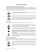
SAFETY INSTRUCTIONS 1. Installation, Operation and Service Precautions This product is designed for use in accordance with EN 61010-1 and UL 3101 for Installation Category 2, Pollution Degree 2. Hazardous voltages are present within this product during normal operation.
OPERATOR SAFETY INSTRUCTIONS Read these safety instructions, as well as the applicable installation and operating instructions contained in this manual before using the power supply. WARNING Do not touch the output terminals. The output is dangerous. Electric shock can cause injury or death. Do not remove the cover or disassemble the unit. There are no operator serviceable components or adjustments inside the unit.
LIST OF WARNINGS AND CAUTIONS PAGE WARNING/CAUTION 3-8 WARNING: For inductive loads, and especially superconducting magnet type loads, 3-9 WARNING: For both inductive loads and constant-current-type active electronic 3-9 WARNING: Accessing the BOP after the output is disabled in BATTERY mode is haz- 4-8 WARNING: The sense resistor will be dissipating full rated current of the BOP.
LIST OF WARNINGS AND CAUTIONS PAGE WARNING/CAUTION 2-14 CAUTION: Do not connect both the load and the programming device return (common) to earth-ground potential. Otherwise, If the COMMON power connection between the BOP and the load is lost, then the BOP can be damaged by output current flowing inside the BOP along the programming signal return path.
TABLE OF CONTENTS SECTION PAGE SECTION 1 - INTRODUCTION 1.1 1.2 1.3 1.4 1.5 1.5.1 1.5.2 1.5.3 1.5.4 1.5.5 1.5.6 1.5.7 1.5.8 1.5.9 1.6 1.7 1.8 Scope of Manual ..................................................................................................................................... 1-1 General Description................................................................................................................................. 1-1 Specifications .............................................
TABLE OF CONTENTS SECTION PAGE SECTION 3 - OPERATION 3.1 3.2 3.2.1 3.3 3.3.1 3.3.2 3.3.2.1 3.3.2.2 3.3.3 3.3.4 3.3.4.1 3.3.5 3.3.6 3.3.7 3.3.8 3.3.9 3.3.9.1 3.3.9.2 3.3.9.3 3.3.9.4 3.3.10 3.3.11 3.4 3.4.1 3.4.1.1 3.4.1.2 3.4.2 3.4.2.1 3.4.3 3.5 3.5.1 3.5.2 3.5.3 3.5.4 3.5.4.1 3.5.4.2 3.5.5 3.5.5.1 3.5.5.2 3.5.6 3.5.7 3.5.7.1 3.5.7.2 3.5.7.3 3.5.7.4 3.5.7.5 3.5.8 3.5.9 3.6 3.6.1 3.6.2 3.6.3 3.6.3.1 3.6.3.1.1 3.6.3.1.2 3.6.3.1.3 ii General ..................................................................
TABLE OF CONTENTS SECTION PAGE 3.6.4 RS232-C Operation ........................................................................................................................... 3-30 3.6.4.1 Serial Interface............................................................................................................................. 3-30 3.6.4.2 RS 232 Implementation ............................................................................................................... 3-30 3.6.4.2.
TABLE OF CONTENTS SECTION PAGE SECTION 4 - CALIBRATION 4.1 4.2 4.3 4.3.1 4.3.2 4.4 General ................................................................................................................................................... Test Equipment Requirements ............................................................................................................... Calibration using Remote SCPI commands via GPIB or RS 232 Interface ............................................
TABLE OF CONTENTS SECTION B.26 B.27 B.28 B.29 B.30 B.31 B.32 B.33 B.34 B.35 B.36 B.37 B.38 B.39 B.40 B.41 B.42 B.43 B.44 B.45 B.46 B.47 B.48 B.49 B.50 B.51 B.52 B.53 B.54 B.55 B.56 B.57 B.58 B.59 B.60 B.61 B.62 B.63 B.64 B.65 B.66 B.67 B.68 B.69 B.70 B.71 B.72 B.73 B.74 B.75 B.76 B.77 B.78 B.79 B.80 B.81 B.82 PAGE [SOURce:]CURRent[:LEVel]:LIMit:POS? Query................................................................................... [SOURce:]CURRent:MODE Command.......................................
TABLE OF CONTENTS SECTION B.83 B.84 B.85 B.86 B.87 B.88 B.89 B.90 B.91 B.92 B.93 B.94 B.95 B.96 B.97 B.98 B.99 B.100 B.101 B.102 B.103 B.104 B.105 B.106 B.107 B.108 B.109 B.110 B.111 B.112 B.113 B.114 B.115 B.116 B.117 B.118 B.119 B.120 B.121 B.122 B.123 B.124 B.125 B.126 B.127 B.128 B.129 B.130 B.131 B.132 B.133 B.134 B.135 B.136 B.137 B.138 B.139 vi PAGE [SOURce:]LIST:WAIT:HIGH Command .................................................................................................
TABLE OF CONTENTS SECTION B.140 B.141 B.142 B.143 B.144 B.145 B.146 B.147 B.148 PAGE SYSTem:PASSword:STATe? Query ..................................................................................................... SYSTem:REMote Command................................................................................................................. SYSTem:REMote? Query......................................................................................................................
LIST OF FIGURES FIGURE 1-1 1-2 1-3 2-1 2-2 2-3 2-4 2-5 2-6 2-7 2-8 2-9 2-10 2-11 3-1 3-2 3-3 3-4 3-5 3-6 3-7 3-8 3-9 3-10 3-11 3-12 4-1 4-2 A-1 B-1 B-2 B-3 B-4 B-5 B-6 B-7 B-8 B-9 B-10 B-11 B-12 B-13 viii TITLE PAGE High Power BOP-GL Series Power Supply................................................................................................... x BOP-GL Power Supply, Outline Drawing ...................................................................................................
LIST OF TABLES TABLE 1-1 1-2 1-3 1-4 1-5 2-1 2-2 2-3 2-4 2-5 2-6 2-7 2-8 2-9 2-10 2-11 2-12 3-1 3-2 3-3 3-4 3-5 3-6 3-7 3-8 3-9 3-10 3-11 4-1 4-2 4-3 4-4 4-5 A-1 A-2 A-3 A-4 B-1 B-2 B-3 B-4 B-5 TITLE PAGE BOP-GL 1000 Watt Model Parameters .......................................................................................................1-1 BOP General Specifications .......................................................................................................................
FIGURE 1-1.
SECTION 1 - INTRODUCTION 1.1 SCOPE OF MANUAL This manual contains instructions for the installation, operation and servicing of the BOP-GL series of 1000 Watt rack-mounted, 4-quadrant bipolar, programmable, voltage and current stabilized d-c power supplies manufactured by Kepco, Inc., Flushing, New York, U.S.A. 1.2 GENERAL DESCRIPTION The BOP-GL Series (Figure 1-1), are true 4-quadrant programmable voltage and current power supplies, meaning they are capable of both sourcing and sinking power.
TABLE 1-2. BOP GENERAL SPECIFICATIONS SPECIFICATION RATING/DESCRIPTION CONDITION INPUT CHARACTERISTICS A-C Voltage nominal 230 Va-c range Frequency Current 176 - 264 Va-c nominal 50-60 Hz range 47 - 63 Hz 176 Va-c 264 Va-c Power factor 6.4A maximum Sink 0.97 minimum EMC Compliance EMC emissions maximum 0.99 minimum Switching frequency EMC immunity to: 9.
TABLE 1-2. BOP GENERAL SPECIFICATIONS (Continued) SPECIFICATION RATING/DESCRIPTION CONDITION OUTPUT CHARACTERISTICS (Continued) Analog Programming accuracy Voltage Voltage • The programming signal is +1V to +10V for 10% to 100% of all four limits (±voltage, ±current) • Input impedance is 20KOhms for the main channel (voltage or current) • When the limit channels are not used, the limits are clamped to 1% above the nominal values. • The limit source must be able to sink a maximum 0.
TABLE 1-2. BOP GENERAL SPECIFICATIONS (Continued) SPECIFICATION RATING/DESCRIPTION CONDITION OUTPUT CHARACTERISTICS (Continued) Error sensing Transient recovery in voltage mode 0.
TABLE 1-2. BOP GENERAL SPECIFICATIONS (Continued) SPECIFICATION RATING/DESCRIPTION CONDITION Main channel (voltage or current) –10V to +10V Full range output, 20K Ohm input impedance Protection Limit channels: +Voltage, –Voltage +Current, –Current +1V to +10V 10% to 100% of Nominal Range. Input voltage clamped to 12V through 1K ohms. Maximum of 0.15mA input current at 1V input voltage. ±Voltage protection controllable in Current Mode, ±Current protection limits controllable in Voltage mode.
TABLE 1-2. BOP GENERAL SPECIFICATIONS (Continued) SPECIFICATION RATING/DESCRIPTION CONDITION PROGRAMMING CHARACTERISTICS (Continued) Digital control Status Display remote IEEE 488-2 (GPIB) and RS 232 remote RS 485 (BITBUS) SCPI IEEE 1118, used for series and parallel configurations front panel Lights: Unit Status: POWER / FAULT/LIMIT (lights green for Power OK, lights red for Fault, lights orange for Limit). Output Status: OUTPUT ON (lights green On, not lit for Off).
TABLE 1-2. BOP GENERAL SPECIFICATIONS (Continued) SPECIFICATION RATING/DESCRIPTION CONDITION FUNCTION GENERATOR CHARACTERISTICS (Continued) Basic waveform parameters Sine: Frequency (Hz), Amplitude (Vp-p or Ap-p), Offset (Vd-c or Ad-c), Start Phase (°), Stop Phase (°). Triangular: Frequency (Hz), Amplitude (Vp-p or Ap-p), Offset (Vd-c or Ad-c), Start Phase (°), Stop Phase (°). Ramp (Pos. or Neg.): Frequency (Hz), Amplitude (Vp-p or Ap-p), Offset (Vd-c or Ad-c).
TABLE 1-2. BOP GENERAL SPECIFICATIONS (Continued) SPECIFICATION RATING/DESCRIPTION CONDITION FUNCTION GENERATOR CHARACTERISTICS (Continued) Amplitude Range Main Channel Voltage (Volts p-p) 0 to 2 x EONOM Sine, Triangle, Square, ±Ramp Current (Amperes p-p) 0 to 2 x IONOM Sine, Triangle, Square, ±Ramp Protection Limit Channel .
TABLE 1-2. BOP GENERAL SPECIFICATIONS (Continued) SPECIFICATION RATING/DESCRIPTION CONDITION SAVE/RECALL CHARACTERISTICS (See PAR. 3.5.7) Number of Locations 99 Parameters Saved or Recalled 15 locations available to be implemented on power-up All parameters saved for power-up Mode of operation Voltage, Current or External Reference type For External the operating mode is determined by signal at I/O Port; no signal selects voltage mode (see PAR. 3.4.1).
TABLE 1-2. BOP GENERAL SPECIFICATIONS (Continued) SPECIFICATION RATING/DESCRIPTION CONDITION GENERAL (ENVIRONMENTAL) CHARACTERISTICS Temperature operating storage 0 to +50 deg C -20 to +85 deg C Cooling Two internal fans Humidity 0 to 95% RH Shock Vibration 20g.
1.738 [44.15] 23.863 [606.12] 22.000 [558.79] 21.564 [547.73] 20.000 [508.00] 21.439 [544.54] 22.800 [579.11] 18.805 [477.63] 18.018 [457.64] 17.675 [448.93] 16.835 [427.60] FIGURE 1-2. BOP-1K-GL 022814 18.235 [463.16] 18.985 [482.21] 2.215 [56.27] 1.470 [37.34] 5.218 [132.54] OBROUND 0.25x0.453 (4 LOC.
REAR VIEW SEE DETAIL "A". 22.000 [558.79] SLIDES TRAVEL DISTANCE: 23.000 [584.2] SEE NOTE 6. DETAIL "A" FIGURE 1-2.
1.4 REMOTE CONTROL The BOP Power Supply can be remotely controlled directly using either a) analog signal applied to the Analog I/O Port (see PAR. 3.6 for details) or b) digital commands via either the IEEE 488.2 (GPIB) bus (see PARs. 3.6.3) or RS232C interface (see PAR.3.6.4) using IEEE 488 and SCPI commands (see and Appendix A and B, respectively).
1.5.4 SAVING AND RECALLING SETTINGS The BOP offers 99 memory locations that can be used to store a set of operating parameters for later use. For each location, the user can store operating mode, output on/off, Main channel reference type and value, and protection reference type and value. The stored settings can then be recalled to quickly program the unit to the predetermined setting.
1.6 EQUIPMENT SUPPLIED Equipment supplied with the BOP power supply is listed in Table 1-3. TABLE 1-3. EQUIPMENT SUPPLIED ITEM FUNCTION PART NUMBER Source Power Entry mating connector Mates with source power entry connector 142-0381 (Kepco) (IEC 320) PAR/SER CONTROL - IN mating connector Mates with PAR/SER CONTROL - IN port to allow access to pins required for calibration 142-0488 (Kepco) Mating Connector, Trigger Mates with Trigger port.
FIGURE 1-3.
TABLE 1-5. ACCESSORIES ITEM FUNCTION PART NUMBER Mating Connector, Trigger Mates with Trigger port. 142-0527 (Kepco) SP2501 (CUI Stack) IEEE 1118 (BITBUS) Mating connector Allows connection to IEEE 1118 (BITBUS) port. 142-0485 (Kepco) KMDLA-5P (Kycon Inc.) IEEE 488 Cable, (1 meter long) Connects BOP power supply to GPIB bus. SNC 488-1 IEEE 488 Cable, (2 meter long) Connects BOP power supply to GPIB bus. SNC 488-2 IEEE 488 Cable, (4 meter longs) Connects BOP power supply to GPIB bus.
SECTION 2 - INSTALLATION 2.1 UNPACKING AND INSPECTION This instrument has been thoroughly inspected and tested prior to packing and is ready for operation. After careful unpacking, inspect for shipping damage before attempting to operate. Perform the preliminary operational check as outlined in PAR. 2.3. If any indication of damage is found, file an immediate claim with the responsible transport service. 2.2 TERMINATIONS AND CONTROLS a) Front Panel: Refer to Figure 3-1 and Table 3-1.
TABLE 2-1.
VOLTAGE MONITOR FULL SCALE ADJ (A2A5R89) VOLTAGE MONITOR ZERO ADJ A2A5R85 CALIBRATION ADJUSTMENTS S3 S2 S1 POWER-UP SETUP SWITCHES FIGURE 2-2. BOP-GL TOP COVER ACCESSIBLE COMPONENTS TABLE 2-2. POWER-UP SETUP SWITCHES SWITCH (FIGURE 2-2) S1 SECTION FUNCTION DESCRIPTION S1-1 Bit 1 (LSB) S1-2 Bit 2 S1-3 Bit 3 S1-4 Bit 4 S1-5 Bit 5 (MSB) 1. Enable the GPIB address from 0 [00000] to 30 [11110]) while reading powerup switches S2 and S3 during a normal power-up (see PAR. 3.3.2.2 for details).
TABLE 2-2. POWER-UP SETUP SWITCHES (CONTINUED) SWITCH (FIGURE 2-2) SECTION FUNCTION DESCRIPTION S3-1 (LSB) Function established by S3-5 S3-5 determines the function of S3-1 through S3-4: S3-5 = 1: S3-1: Voltage mode (1) or Current mode (0) S3-2 S3-2: Analog Input ON (1) or Analog Input OFF (0) Analog input ON enables pin 11 of the I/O port. S3-3 S3-3 and S3-4 determine limits upon power-up: S3-4 (MSB) S3-4 S3-3 0 0 0 1 Digital –V and –C Prot Max (Internal) set to max.
TABLE 2-4. TRIGGER PORT PIN ASSIGNMENTS CONNECTOR PIN SIGNAL NAME FUNCTION 1 LOGIC GND Return for EXT TRIGGER and REMOTE ON-OFF signals. 2 REMOTE ON-OFF Logic 0 or short-circuit referenced to logic GND (pin 1) sets the output OFF (output disabled). Logic 1 (TTL or 5VCMOS) or open sets the output to ON (output enabled). This logic can be reversed (see 3.3.2.1 for details.).
TABLE 2-6. RS232C PORT INPUT/OUTPUT PIN ASSIGNMENTS CONNECTOR PIN RS 232 PORT A1J5 SIGNAL NAME FUNCTION 1 RTS Request To Send (protocol not used) 2 RXD Receive Data 3 TXD Transmit Data 4 LOGIC GND Logic Ground 5 LOGIC GND Logic Ground 6 CTS Clear To Send (protocol not used) TABLE 2-7.
TABLE 2-9. PARALLEL/SERIAL PROTECT IN PORT PIN ASSIGNMENTS CONNECTOR PIN SIGNAL NAME SD_A Anode of LED optocoupler which is part of protection circuit for parallel or series combination. Cathode of LED is connected to PARALLEL/ SERIAL PROTECT OUT PORT (A2A5J2) pin 1 (see Table 2-10). When activated, the optocoupler shuts down the unit. LEDs from all units of the parallel or series combination are connected in series.
TABLE 2-11. ANALOG I/O PORT INPUT/OUTPUT PIN ASSIGNMENTS CONNECTOR PIN SIGNAL NAME FUNCTION CAUTION: it is recommended that source power of external equipment connected to the Analog Port be applied through an isolating transformer to avoid ground loops or possible damage to the BOP due to incorrect equipment a-c wiring (e.g., defeating of ground connection).
TABLE 2-12. IEEE 488 PORT INPUT/OUTPUT PIN ASSIGNMENTS CONNECTOR IEEE 488 PORT J5 2.
S1: 00110 = GPIB ADDRESS 6 S2: 00001 = STANDALONE S3: 11111 = VOLTAGE MODE, ANALOG INPUT ON ±V AND ±C PROTECT MAX SET TO MAXIMUM FIGURE 2-3. FACTORY DEFAULT POWER-UP SWITCH SETTINGS 2. Connect a twisted wire pair (either #24 or #22 AWG) to the mating connector for the Analog I/O port pins 11 and 10. Connect +10V d-c ±0.1mV to pin 11, referenced to pin 10, then install the mating connector on the Analog I/O port at the rear panel.
CAUTION: DO NOT repeatedly toggle the POWER circuit breaker/switch as this may damage the unit. 5. Connect the power supply to source power (see PAR. 2.5.2). With no load connected, set POWER switch to the ON position. 6. Each time the unit is turned on an internal self-test is performed.
2.5 WIRING INSTRUCTIONS Interconnections between an a-c power source and a power supply, and between the power supply and its load are as critical as the interface between other types of electronic equipment. If optimum performance is expected, certain rules for the interconnection of source, power supply and load must be observed by the user. These rules are described in detail in the following paragraphs.
empirical testing. If there is a choice in selecting either the OUTPUT or COMMON output terminals of the power supply for the d-c ground point, both sides should be tried, and preference given to the ground point producing the least noise. For single, isolated loads the d-c ground point is often best located directly at one of the output terminals of the power supply; when remote error sensing is employed, d-c ground may be established at the point of sense lead attachment.
acteristics; or where the dynamic output response of the power supply is critical to load performance. 2.5.5 LOAD CONNECTION - GENERAL Load connections require wires that are properly rated for the nominal output current of the unit. Load connections to the BOP power supply are achieved via the OUTPUT and COMMON bus bar-type terminals located on the rear panel. A barrier strip is provided at the rear panel for connection of the sense wires to the load (for remote sensing or multiple unit applications).
2.6 COOLING The power devices used within the power supply are maintained within their operating temperature range by means of internal heat sink assemblies and by two cooling fans. Periodic cleaning of the power supply interior is recommended. Do not obstruct any vents on the unit.
FIGURE 2-4. N/C OUT S OUT MON GND GND NET FIGURE 2-5.
2.7.2 SETUP FOR ANALOG CONTROL 1. With power off configure the power-up setup switches (see Table 2-2 for details). Setup for analog control can be accomplished through the power-up switches in one of two ways: a.
ANALOG PROGRAMMING SOURCE FOR MAIN CHANNEL H L 0 TO ±10V ANALOG I/O PORT TWISTED < 1Ω 20KΩ 11 10 +1 TO +10V TWISTED < 1Ω 0 TO 10V 100KΩ 13 14 5 6 12 SEE WARNING VM DVM (OUTPUT VOLTAGE MEASUREMENT) SEE WARNING ANALOG H1 PROGRAMMING SOURCE FOR H2 PROTECTION LIMIT CHANNELS L PROGRAMMING SOURCE FOR MODE CONTROL BOP-GL POWER SUPPLY H L OUTPUT TERMINALS L OUT OUT MON OUT S COMM S COMM MON COMM 1.
2.8 MULTIPLE UNIT CONFIGURATIONS Parallel and series configurations of identical BOP units increase the rated voltage and current range of the power supply. Up to two units (three units for model BOP 10-100GL) can be connected in parallel to increase the current: IMAX (one unit) x NP = IMAX (parallel combination) where NP = number of units in parallel.
NOTE: Consult factory for configurations requiring more than two units in parallel. FIGURE 2-7.
NOTE: Consult factory for configurations requiring more than two units in parallel. FIGURE 2-8.
N/C OUT S OUT MON GND GND NET COM COM MON S N/C OUT S OUT MON GND GND NET COM COM MON S N/C OUT S OUT MON GND GND NET COM COM MON S NOTE: Consult factory for configurations requiring more than two units in series. FIGURE 2-9.
N/C OUT S OUT MON GND GND NET COM COM MON S N/C OUT S OUT MON GND GND NET COM COM MON S N/C OUT S OUT MON GND GND NET COM COM MON S NOTE: Consult factory for configurations requiring more than two units in series. FIGURE 2-10.
2.8.2 MULTIPLE UNIT SOURCE POWER When multiple units are connected in series or parallel, the individual power supplies of the system may be connected to different phases of a 3-phase a-c power source. 2.8.3 MULTIPLE UNIT PROTECTION For multiple unit configurations it is necessary to configure the protection so that a fault will shut down all the interconnected power supplies. Figure 2-11 is a simplified diagram showing typical protection interconnections for master/slave configurations.
2.8.4 OPERATING INSTRUCTIONS FOR MULTIPLE UNIT COMBINATIONS 1. Before either installing the units in a rack or stacking and connecting them one on top of the other, configure the power-up settings as desired while the units are turned off. a. For master unit, perform the Reset Power-up (see PAR. 3.3.2.1) to establish the load type, logic for trigger port pin 2 (output on/off) and RS 232 baud rate (this also resets limits to factory default settings (see PAR. B.143). b.
7. If analog programming is to be used, connect the programming device to the master as shown in Figure 2-6. 8. If analog control is to be used, the multiple unit combination is ready for use. Operation of the multi-unit combination is identical to a standalone unit. NOTE: When powering down the system, the master should be the last unit turned off. 9. If digital control is to be used, turn all units off. a.
SECTION 3 - OPERATION 3.1 GENERAL This section explains how to operate the 1000 Watt BOP-GL Power Supply. The power supply can be operated using either a) signals applied to the Analog I/O port control or b) digital commands via either the GPIB or RS 232 bus or c) a mixture of both. Analog control (see PAR. 3.
• Voltage mode (Current mode) • internal control, ± limit values at max (1.01 x EOnom or IOnom) (internal control, +limit values at maximum (1.01 x EOnom or IOnom), –limit values at minimum (box)) (internal control, –limit values at maximum (1.
FIGURE 3-1. BOP-GL SERIES FRONT PANEL TABLE 3-1. FRONT PANEL CONTROLS AND INDICATORS NUMBER (FIGURE 3-1) CONTROL/INDICATOR 1 POWER ON/OFF circuit breaker A7CB1 2 OUTPUT ON LED 3 Unit Status POWER/FAULT/LIMIT LED 4 Configuration Type MASTER/SLAVE LED Lights green for MASTER or Standalone, lights yellow for SLAVE. For multiunit configuration, this flashes (either green or yellow) to indicate unit is a master, and is looking for slaves. If flashing continues, refer to PAR. 3.8 for troubleshooting.
3.3.2.1 RESET POWER-UP At power up, if the GPIB address switches (S1) are set to all ones (address 31), the unit does a reset power-up to establish the load type, baud rate and Remote On/Off logic of Trigger port pin 2. Reset power-up also causes the unit to reset all limits to the factory default configuration (see PAR. B.143) and override limits saved by MEM:UPD LIM command. If load type, baud rate and Trigger Port remote on/off logic do not need to be changed, refer to PAR. 3.3.2.2 for normal power-up.
b. Set S2 to select standalone or multiple unit operation. c. Set S1 with valid GPIB address from 0 to 30. CAUTION: DO NOT repeatedly toggle the circuit breaker/switch as this may damage the unit. 2. Set POWER ON/OFF circuit breaker/switch (1, Figure 3-1) on front panel to ON. If actuator does not lock when released, wait a few seconds before trying again. The circuit breaker is “trip-free” design; if overload exists, contacts cannot be held closed by actuator. 3.
TABLE 3-2. VOLTAGE AND CURRENT PARAMETER DEFINITIONS Term Definition To modify refer to PAR. +EOnom –EOnom The nominal (rated) output voltage of the unit determined by model; e.g. for a BOP 36-28GL, ±EOnom is 36V. N/A +IOnom –IOnom The nominal (rated) output current of the unit determined by model; e.g. for a BOP 36-28GL, ±IOnom is 28A. N/A +Voltage –Voltage Voltage mode only. Positive (+) and negative (–) output voltage values established by remote command.
3.3.5 MAXIMUM ACCEPTED VOLTAGE OR CURRENT (MAIN CHANNEL SOFTWARE LIMITS) The software limits for the main channels (+Voltage Max, –Voltage Min, +Current Max and – Current Min) are the maximum (positive) and minimum (Maximum negative) values allowable for voltage and current. The default software limits are determined by the model: the nominal (rated) values for voltage and current (e.g., 36V and 28A for the BOP 36-28GL). These four values can be adjusted independently.
To ensure these settings are restored after a power cycle send MEM:UPD LIM and tag the unit with the new power-up configuration. To restore factory default limits and undo the limits saved by MEM:UPD LIM command, perform a reset power-up (see PAR. 3.3.2.1). 3.3.6 MAXIMUM/MINIMUM PROTECTION LIMITS (SOFTWARE-CONTROLLED) The ± protection limits are software limits that establish the maximum and minimum (maximum negative) allowable levels of output voltage in current mode and current in voltage mode.
mode, voltage is set to zero and both current protect and voltage limit are set to maximum. When the unit is enabled, the pre-existing settings for voltage, current protect and voltage limit are restored. WARNING For both inductive loads and constant-current-type active electronic loads when the BOP output is set to OFF, a path is provided for absorbing either the energy accumulated in the reactance of the load during the ON state, or energy delivered by an electronic load.
TABLE 3-3. POWER SUPPLY BEHAVIOR WHEN OUTPUT IS SET TO OFF LOAD TYPE SETTING If unit was in Voltage Mode when output OFF command issued. If unit was in Current Mode when output OFF command issued. ACTIVE • • • • Unit remains in voltage mode. Voltage set to zero. Both ± Current Protect set to maximum. Both ± Voltage Limit remain at maximum. • • • • Unit set to voltage mode. Voltage set to zero. Both ± Current Protect remain at maximum. Both ± Voltage Limit set to maximum.
3.3.9.1 REMOTE SHUTDOWN Functionality of a standalone unit can be shut down using a remote signal applied to the PROTECT EXT. PORT as shown in Figure 3-2 or 3-3. Functionality of a multiple unit configuration (parallel, series or series-parallel) can be shut down by applying a remote signal to the master PAR/SER PROTECTION PORT as shown in Figure 3-2 or 3-4.
FIGURE 3-4. 3.3.9.2 REMOTE SHUTDOWN USING INTERNAL POWER, MULTIPLE UNITS, REMOTE ON-OFF USING TRIGGER PORT PIN 2 A standalone unit or a multiple unit configuration (parallel or series) can be set to output on (enabled) or off (disabled) by applying a remote signal to the TRIGGER PORT as shown in Figure 3-5. For multiple unit configurations this signal must be applied to the master. The factory default condition, established by the Reset Power-up configuration (see PAR. 3.3.2.
FIGURE 3-5. 3.3.10 REMOTE ON-OFF, STANDALONE OR MULTIPLE UNITS SETTING MAIN CHANNEL MODE (VOLTAGE OR CURRENT) When the unit is turned on, the main channel mode is determined by the power-up switches. • If S3 is set to 00000 the mode is determined by the status of pin 2 of the Analog I/O port (see Table 2-11). Applying a TTL logic 1 (or open circuit) programs the unit to voltage mode. Applying a TTL logic 0 (or short circuit) programs the unit to current mode.
• If S3 is set to 101xx (x = set as desired, S3-3 = 1, S3-4 = 0, S3-5 = 1), –V Protect Max and –C Protect Max are internally set to maximum (1.01 x nominal (rated) values. +V Protect Max and +C Protect Max are Internally set to min. (box). • If S3 is set to 110xx (x = set as desired, S3-3 = 0, S3-4 = 1, S3-5 = 1), +V Protect Max and +C Protect Max are internally set to maximum (1.01 x nominal (rated) values. –V Protect Max and –C Protect Max are Internally set to min. (box).
Pins of the Analog I/O port can also be used selectively to control the unit if the unit is powered up with power-up switches S3-2 and S3-5 set to on (see Figure 2-2 and Table 2-2). This allows the other S3 switches to selectively establish the following: 3.4.1 • Establish voltage or current mode (PAR. 3.3.10). • Control the main channel using the BOP as a power amplifier (PAR. 3.4.1). • Establish the protection limits (PAR. 3.4.2).
and rises to +10V causes the output to rise from zero and reach +18V when the external reference reaches +5V. The output stays at +18V while the reference increases from +5V to +10V since the system voltage limits for this example are ±18V. The command sequence that can be used is: FUNC:MODE VOLT Sets unit to voltage mode. VOLT:LIM 18 Sets main channel (voltage) software limits to ±18V. CURR:PROT 20 Sets protection level to ±20A. To restore all the above settings for power up, send *SAV3.
saved settings upon power up: output set to voltage (gain) mode of operation with gain set to 2.9. The gain in voltage mode is GV = VSET/10 where VSET is the desired full scale voltage (in Volts) entered at the front panel. The gain in current mode is GA = ISET/10 where ISET is the desired full scale current (in Amperes) entered at the front panel. NOTE: If the system limits have been modified (PAR. 3.3.5), the output of the power supply will never exceed the modified system limits. 3.4.
3.4.2.1 USING LESSER OF DIGITAL VS. ANALOG (EXTERNAL) LIMITS The BOP provides the ability to automatically choose the lesser absolute value between the external limits (applied to Analog I/O port pins 5, 6, 13 and 14) and the limits established by a digital command. This feature is accessible through digital control and can be restored upon power-up using a saved location.
channel is determined automatically by the main channel selected. When Voltage mode is selected, the current protection limit channel is active, and when Current mode is selected, the Voltage protection limit channel is active. 3.5.3 PROGRAMMING VOLTAGE OR CURRENT AND ASSOCIATED PROTECT LIMITS When the operating mode is Voltage mode, use the VOLT command (see PAR. B.86) where = digits with decimal point and Exponent, e.g., 2.71E1 for 27.1. For example, send VOLT 2.
±voltage protection (±V Protect) can be set to. If the programmed values are exceeded, a command error -201, Voltage Range error” occurs. +V Protect and –V Protect are programmed using the VOLT:PROT commands (see PAR’s. B.29 through B.36 for details.) These commands program the ±voltage protection values. If load voltage reaches the ±voltage protection values, voltage will be clamped so ±voltage protection values cannot be exceeded. 3.5.5 PROGRAMMING TECHNIQUES TO OPTIMIZE PERFORMANCE 3.5.5.
becomes set, the unit is ready for its next command after reading back the data from the query that was added to the command string. When sending the above commands via the RS 232 bus, data flow control must be enabled (XON) for the unit to properly update flash memory. The *OPC? query is ideal to check if the previous command is complete since it returns either a 1 or 0. It is important that it be sent as a part of the same string as the command that causes a flash update.
#include #include #include #include /*Overhead for the use of a NATIONAL INSTRUMENTS gpib interface */ int unit_desc; // handle for the national instruments controller int GPIbus=0; // GPIB card 0 int adr=6; // Power Supply address char status_byte; // status byte from the power supply #define MAV 0x10 /* bit 4 of the status byte is the Message AVailable bit by 488.
3.5.7.2 UNDERSTANDING HOW WAVEFORMS ARE GENERATED Waveform are generated by the BOP by producing a series of discrete output levels (points) in a prescribed pattern. In the case of sine, triangle and ramps, this produces an output that conforms to an approximation of the selected waveform type. The number of points available for a waveform is limited to 3933 for all segments.
TABLE 3-5. SQUARE WAVEFORM FREQUENCY VS. POINTS Frequency (See Note) Total Points From To 0.02Hz 1.8Hz 1.81Hz 2.71Hz Frequency (See Note) Total Points From To 3840 43.51Hz 58.0Hz 2.7Hz 2880 58.01Hz 72.5Hz 90 4.0Hz 1920 72.51Hz 87.0Hz 72 4.01 5.4Hz 1280 87.01Hz 108.7Hz 60 5.41 7.2Hz 960 108.71Hz 145.0Hz 48 120 7.21Hz 10.8Hz 720 145.2.9Hz 174.0Hz 36 10.81 16.3Hz 480 174.1Hz 217.5Hz 30 16.31Hz 21.7Hz 320 217.6Hz 261.0Hz 24 21.71Hz 27.1Hz 240 261.
It is recommended that an oscilloscope be used to view the output. CAUTION: The oscilloscope must be floating before connecting to the OUT MON or OUT S terminals or the COM MON or COM S terminal of the BOP. Connect the oscilloscope across OUT S and COM S terminals of the rear panel terminal block to monitor the output at the load, or between OUT MON and COM MON to monitor the BOP output at the BOP (see Figure 2-1). TABLE 3-6.
LIST:CLE Clears the list. Lists are not automatically deleted, but cannot be saved for power-up. LIST:VOLT:APPL LEV,.001,1.5 Sets the first segment at 1.5 volts for 1 millisecond. LIST:VOLT:APPL LEV,.002,0 Sets the zero segment for 2 milliseconds. 2. Send the following commands to create another segment which is the first quadrant of a 20V p-p sine wave riding on a 0V offset. It starts at 0V and rises to 10V (1/2 of 20) over 10 ms (1/4 of 40ms period established by 25Hz frequency).
control whether the *RST command sets the output on or off. The *RST command can be configured using the SYST:SET command (PAR. B.144). TABLE 3-7. OPERATION OF #RST COMMAND Load type when *RST Issued (see NOTE) • Active or Resistive Load (see PAR. 3.5.5) BOP Status After *RST Issued • Voltage mode • Main Channel reference set to 0.0V • Current protect set to 5% of IOnom • Voltage protect set to 5% above EOnom • Battery Load (see PAR. 3.5.
3.6.1 BIT 4882 COMPATIBILITY. To replace a standard low power BOP/BIT 4882 card combination with a 1KW BOP-GL with minimal reconfiguration of existing test setups, send SYSTem:SET 4882 followed by MEMory:UPDate INTERFACE. 3.6.2 BIT 4886 COMPATIBILITY To replace a standard low power BOP/BIT 4886 card combination with a 1KW BOP-GL with minimal reconfiguration of existing test setups, send SYSTem:SET 4886. 3.6.
TABLE 3-9. IEEE 488 (GPIB) BUS COMMAND MODE MESSAGES (CONTINUED) MESSAGE DESCRIPTION MNEMONIC COMMENTS IFC Interface Clear Received MLA My Listen Address Received MTA My Talk Address Received OTA Other Talk Address Received RFD Ready for Data Received or Sent SDC Selected Device Clear Received SPD Serial Poll Disable Received SPE Serial Poll Enable Received SRQ Service Request Sent UNL Unlisten Received UNT Untalk Received TABLE 3-10.
3.6.3.1.3 DETERMINING WHETHER *RST COMMAND SETS THE OUTPUT OFF OR ON Refer to PAR. B.144 (RO0 or RO1) to configure how the unit responds to the *RST (reset) command. See PAR. 3.5.8 to understand how the unit behaves when output is off (disabled) or on (enabled) with different load types. 3.6.4 RS232-C OPERATION The BOP may be operated via an RS232-C terminal, or from a PC using a terminal emulation program.
The BOP provides an additional option that allow handshake communication: the Prompt method. By using the handshake options (prompt and XON XOFF) the host controller can ensure that serial data interrupts occurring after parsing of the incoming message do not result in lost data. Figure 3-8 illustrates the echo mode, the prompt method and the default XON XOFF method described in the following paragraphs. FIGURE 3-8.
The CAN character resets the receive and transmit pointers and queues. CAUTION: When the serial port has received an XOFF, the error message -400, QUE error will be placed in the queue to indicate the loss of transmitted information due to a received XOFF character. When XON is received, the unit will transmit all data in it's buffer followed by the exclamation character (!).
3.6.4.3 RS 232 SERIAL PORT SETUP The unit must be in remote mode before the RS 232 commands to affect the output can be executed (e.g., VOLT 10;OUTP ON). This can be accomplished by sending SYST:REM ON prior to sending any commands that affect the power supply output. (See PAR. B.141 and Figure B-12). Verify that the DIG. CTRL LED on the front panel is lit. Paragraphs 3.6.4.3.1 through 3.6.4.3.4 below describe the commands required for the BOP to communicate via the RS 232C Serial bus using SCPI commands.
Disable - Disables Prompt. If both Serial XON/XOFF and Prompt functions are disabled, Echo mode is the default (see PAR. 3.6.4.2.2 for a description of Xon/Xoff mode). If both Serial Prompt (see PAR. 3.6.4.2.3) and Echo (see PAR. 3.6.4.2.2) modes. are enabled, Prompt is returned when the unit is ready and any received characters are echoed back to the sender. 3.6.5 BOP VISA INSTRUMENT DRIVER The VISA instrument driver for the BOP power supply, available for download at www.kepcopower.com/drivers.
power supply operation (such as setting voltage/current). Common commands and queries are preceded by an asterisk (*) and are defined and explained in Appendix A (see Table 4-4). Refer also to syntax considerations (PARs 3.4.3 through 3.4.6). 3.7.3 SCPI SUBSYSTEM COMMAND/QUERY STRUCTURE Subsystem commands/queries are related to specific power supply functions (such as setting output voltage, current limit, etc.
ments in a single waveform provided the generated points fit in the array. See paragraph 3.5.7.2 for an explanation of how a waveform is generated by the BOP. The following paragraphs provide guidance for using the list commands. 3.7.3.3.1 REQUIRED LIST COMMANDS There are only five LIST commands, plus either the VOLT:MODE (PAR. B.94) or CURR:MODE (PAR. B.27) command, that are needed to create and execute a list.
LIST:VOLT:POINTS? (PAR. B.79) or LIST:CURR:POINTS? (PAR. B.59) These queries return the number of points in a list and provide a simple way to insure that all points entered were properly processed and as intended. 3.7.3.3.4 OPTIONAL COMMANDS Most commands have associated Queries (?) These are useful for troubleshooting/debugging lists but are not needed in most cases. 3.7.3.4 MEASURE SUBSYSTEM This query subsystem returns the voltage and current measured at the power supply's output terminals. 3.7.3.
ROOT : (colon) ABORt subsystem STATus subsystem ABORt STATus :OPERation :CONDition? :ENABle val :ENABle? [:EVENt]? :PRESet :QUEStionable :CONDition? :ENABle val :ENABle? [:EVENt]? INITiate subsystem INITiate [:IMMediate] :CONTinuous bool :CONTinuous? CALibrate subsystem CALibrate :CEXTernal MAX, ZERO :CGAin MIN MAX :CLIMit MAX, ZERO :CPRotect MIN, MAX :CURRent MIN, MAX :DATA val :SAVE :STATe , password :STATe? :VEXTernal MAX, ZERO :VOLTage MIN, MAX :VGAin MIN, MAX :VLIMit MAX, ZERO :V
ROOT : (colon) [SOURce:] subsystem [SOURce:] VOLTage [:LEVel] [:IMMediate] [:AMPLitude] val [:AMPLitude]? MIN, MAX :TRIGgered [:AMPLitude] val [:AMPLitude]? :LIMit[:BOTH] " [:BOTH]? :NEGative " :NEGative? :POSitive " :POSitive? :MODE FIXed, LIST, TRANsient, EXTernal, GAIN, PROTect :MODE? :PROTect [:BOTH] [:BOTH]? :MODE INT, EXT, LESS :MODE? :NEGative :NEGative? :POSitive :POSitive? :LIM[:BOTH] " :LIM[:BOTH]? :LIM:NEGative " :LIM:NEGative? :LIM:POSitive " :LIM:POSitive? " Requires MEM:UPD to save for power-
3.7.3.10 CALIBRATE SUBSYSTEM The BOP series of power supplies support software calibration. A full calibration consist of a voltage calibration and a current calibration. These calibration procedures include steps that prepare the unit for series or parallel operation. Both voltage and current calibrations consist of a zero (performed on the main channels only) and positive and negative full scale calibrations with both internal and external references.
is defined by the way your programming language indicates the end of a line (“newline” character). Sending a character with EOL line asserted is another way of sending a message terminator. The message unit is a keyword consisting of a single command or query word followed by a message terminator (e.g., CURR? or TRIG). The message unit may include a data parameter after the keyword separated by a space; the parameter is usually numeric (e.g.
3.7.4.4 DATA Some commands require data to accompany the keyword either in the form of a numeric value or character string. Data always follows the last keyword of a command or query (e.g., VOLT:LEV:TRIG 14 or SOUR:VOLT? MAX 3.7.4.5 DATA SEPARATOR Data must be separated from the last keyword by a space (e.g.
VOLT:LEV 6;:CURR:LEV 15 The root specifier for VOLT is not necessary because it is the first keyword in the string and has not been included. The second colon is the root specifier for CURR and is required; if it is missing an error will result. The first and third colons are keyword separators. :INIT ON;:TRIG;:MEAS:CURR?;VOLT? colon is a keyword separator. 3.7.4.8 The first three colons are root specifiers. The fourth MESSAGE TERMINATOR The message terminator defines the end of a message.
3.7.6 PROGRAM MESSAGE SYNTAX SUMMARY • Common commands begin with an asterisk (*). • Queries end with a question mark (?). • Program messages consist of a root keyword and, in some cases, one or more message units separated by a colon (:) followed by a message terminator. Several message units of a program message may be separated by a semicolon (;) without repeating the root keyword.
register, and an enable register which allows the contents of the event register to be passed through to set the associated condition register. FIGURE 3-11. STATUS REPORTING STRUCTURE A zero to one transition of a condition register is added to the event register. Reading an event register clears all of the bits found in the event register. If any bits are set in an event register, the following condition register bit is then set.
ANDed with its enable register for all bits except bit 6. The result is placed in bit 6 of the Service Request register. If bit 6 is a 1 (true), it causes the MBT-G power supply to assert the SRQ line to the host controller. Figure 3-11 also shows that if the error/event queue is not empty, bit 3 is set in the Service Request register and bit 4 indicates that a message is available in the output buffer. 3.7.7.
NOTE: If External Reference is enabled and a protection error occurs, both Voltage Protect Error (bit 12) and Current Protect Error (bit 13) are set 3.7.8 • 13 - Current Protect Error — 1 indicates a Current protection error has been detected. • 14 - Sinking — 1 indicates the unit is absorbing energy from the load. • 15 Not Used — always zero. SCPI PROGRAM EXAMPLES Refer to Appendix B, Figures B-1 through B-13 for examples illustrating the use of SCPI commands.
3.8 OPERATOR TROUBLESHOOTING If the unit does not behave as expected, refer to the following procedure for problems that can be corrected without referring the unit for repair. Refer to Figure 2-2 for power-up switch loactions. 1. Immediately after power-up, if the unit beeps in groups of two, power-up switch S2 is incorrectly set up. If the unit beeps in groups of three, power-up switch S3 is improperly setup. If it is beeping on and off, power-up switch S1 is incorrectly set up.
SECTION 4 - CALIBRATION 4.1 GENERAL This section contains the calibration instructions for the Power Supply. It is recommended that the user be familiar with operation of the unit (PAR’s. 3.3 and 3.5) before calibrating the unit. A full calibration consist of a voltage calibration and a current calibration. Both voltage and current calibrations consist of zero, max and min, and protection limit calibration.
TABLE 4-1. CALIBRATION SUMMARY (CONTINUED) Type Step Reference Type and Value Monitored Parameter Output Conditions Notes EXTERNAL CONTROLS, SERIES 1. ZERO 2. POSITIVE External: 1. 0.0V 2. -10.0V (Par/Ser CTRL-IN Port, pin 8 ref to COM S) Output Voltage: 1. 0.0V 2. +10.0V No Load Automatic VM 1. DVM between OUT S and COM S 2. Adjust for zero, +10.0V 3. Calibrate unit for Slave in Series CURRENT, INTERNAL 1. ZERO 2. POSITIVE 3. NEGATIVE Internal Output Current: 1. 0.0A 2. +Current FS 3.
4.2 TEST EQUIPMENT REQUIREMENTS Table 4-2 lists sense resistors recommended for measuring current and includes Kepco and Manufacturer’s part numbers. The value of the sense resistor chosen should be known with 0.001% accuracy. If other than a recommended sense resistor is to be used, it must be rated for at least 100W power dissipation (actual power dissipation will be approximately 10W). The thermal coefficient of the sense resistor chosen should be 10 ppm/°C or better.
a. ZERO Calibrations, main channel (voltage or current) (always done first). The only means of adjustment is the CAL:DATA command which provides a total of 4095 increments of adjustment starting at 0, with 2047 increments in either direction to achieve maximum output levels of ±2.5% of EOnom or IOnom. Adjust the output to obtain the closest value to zero. b. MAX and MIN Calibrations, main channel (voltage or current).
4.3.1 CALIBRATION PROCEDURE USING SCPI COMMANDS The following procedure provides a complete calibration of the unit. Steps 19 and 20 calibrate the control signal used when the unit is a slave in series configurations. Steps 31 and 32 calibrate the control signal used when the unit is a master in parallel configurations. Steps 33 and 34 calibrate the control signal used when the unit is a slave in parallel configurations.
3. Move the DVM to pin 15 referenced to pin 4 of the Analog I/O port. Using an adjustment screwdriver, adjust the ZERO ADJ pot (see Figure 2-2) until the DVM reads 0V ±1mV. Restore the DVM across OUT S and COM S as shown in Figure 4-1. 4. Set the BOP to maximum positive output voltage by sending CAL:VOLT MAX. Measure the voltage output using the DVM. To adjust, send CAL:DATA commands as needed (see PAR. 4.
commands as needed (see PAR. 4.3a) until the DVM reading is as close to zero as possible within tolerance specified in Table 4-3 for VOLTAGE ZERO. 13.Set the BOP to zero volts output by sending CAL:ZERO. Disconnect the +10V d-c reference voltage from the analog I/O port external reference pin (A2A5J6 pin 11) of the BOP, then connect 0V ±0.
resistor ((LO terminal of DVM to common P terminal). Table 4-4 provides recommended sense resistor values for various BOP current outputs, as well as the formula for calculating expected measured values and tolerances for any sense resistor other than those recommended. Table 4-2 lists Kepco and Manufacturer part numbers for those sense resistors recommended. CAUTION WIRES BETWEEN BOP OUTPUT AND SENSE RESISTOR MUST BE RATED TO CARRY THE RATED OUTPUT CURRENT OF THE POWER SUPPLY. AWG#6 IS RECOMMENDED.
24.Set the BOP to maximum negative output current by sending CAL:CURR MIN. Continue to measure the output current of the supply using the DVM connected to the sense resistor. To adjust, send CAL:DATA commands as needed (see PAR. 4.3b) to adjust the BOP output until the DVM reads as close as possible above (absolute value) the nominal full scale value within tolerance specified in Table 4-4 for –FULL SCALE CURRENT. 25.
32.Set the BOP to maximum positive output current by sending CAL:IOUT MAX. With the DVM still connected to pin 6 (IOUT_M_UNIT) referenced to pin 1 (SGND) of the PAR/SER CONTROL IN connector measure the voltage output using the DVM. Send CAL:DATA commands as needed (see PAR. 4.3b) until the DVM reading is +10V ±1.0mV. 33.Send CAL:ZERO to prepare for calibration of S_IN_PARALLEL (slave input) control signal. Connect a 0V ±0.
The Master calibration should never be overwritten. Factory, Master, and First are set to the same values when the BOP is calibrated at the factory. The Working calibration is the active calibration. Each time a CAL:SAV is executed, the values are saved in the Working (active) area. At the same time, the values previously stored in Working are moved to Prior, and the values previously stored in Prior are moved to Oldest. The values previously stored in Oldest are no longer available.
APPENDIX A - SCPI COMMON COMMAND/QUERY DEFINITIONS A.1 INTRODUCTION This appendix defines the SCPI common commands and queries used with the BOP power supply. Common commands and queries are preceded by an asterisk (*) and are defined and explained in paragraphs A.2 through A.18, arranged in alphabetical order. Table A-1 provides a quick reference of all SCPI common commands and queries used in the Interface Card. TABLE A-1. IEEE 488.2 COMMAND/QUERY INDEX A.2 COMMAND PAR. COMMAND PAR. *CLS A.
A.4 *ESE? — STANDARD EVENT STATUS ENABLE QUERY Syntax: *ESE? *ESE? Return value: Integer> value per Table A-2. Description: Returns the mask stored in the Standard Event Status Enable Register. Contents of Standard Event Status Enable register (*ESE) determine which bits of Standard Event Status register (*ESR) are enabled, allowing them to be summarized in the Status Byte register (*STB).
A.8 *OPC? — OPERATION COMPLETE QUERY Syntax: *OPC? *OPC? Return value: <1 or 0> (ASCII) 0 placed in output queue if power supply has not completed operation after prior *OPC command. 1 placed in output queue when power supply has completed operation. Description: Indicates when pending operations have been completed. *OPC command must be sent to first to clear status bit 0 (Operation Complete).
A.9 *OPT? *OPT? — OPTIONS QUERY Syntax: *OPT? Returns string determined by power supply model. Description: Causes the power supply to return an ASCII string which defines the functionality of the power supply. The functionality is defined as follows: STRING DATA CCAL RL1 MEANING Support for limit calibrations is present. Commands sent over GPIB cause unit to enter remote mode. MEMM Computer location commands are supported. LSTAPL LIST Apply command is supported. A.
*SRE A.13 *SRE — SERVICE REQUEST ENABLE COMMAND Syntax: *SRE grammed. where = value from 0 - 255 per Table A-3, except bit 6 cannot be pro- Description: Sets the condition of the Service Request Enable register. The Service Request Enable register determines which events of the Status Byte Register are summed into the MSS (Master Status Summary) and RQS (Request for Service) bits. RQS is the service request bit that is cleared by a serial poll, while MSS is not cleared when read.
*TST? A.17 *TST? — SELF TEST QUERY Syntax: Description: *TST? Returned value: 7 bits coded per Table A-4. Power Supply test.This query causes the power supply to do a self test and provide the controller with pass/fail results. A 0 is returned if the unit passes the test. If the unit fails, a number from 1 through 128 is returned to indicate the cause of the error. The test executes each of the subtests even when any one fails. If any test fails an error code bit is set which is returned to the user.
APPENDIX B - SCPI COMMAND/QUERY DEFINITIONS B.1 INTRODUCTION This appendix defines the SCPI subsystem commands and queries used with the BOP power supply. Subsystem commands are defined in PAR. B.3 through B.148, arranged in groups as they appear in the tree diagram, Figure 3-9. Table B-1 provides a quick reference of all SCPI subsystem commands and queries used in the BOP. TABLE B-1. SCPI SUBSYSTEM COMMAND/QUERY INDEX COMMAND PAR. COMMAND PAR. ABOR B.3 [SOUR:]LIST:CURR, ? B.54, B.55 CAL B.
TABLE B-1. SCPI SUBSYSTEM COMMAND/QUERY INDEX (CONTINUED) COMMAND PAR. COMMAND PAR. [SOUR:]VOLT:PROT:NEG, ? B.100, B.101 SYST:COMM:SER:ECHO, ? B.126, B.127 [SOUR:]VOLT:PROT:POS, ? B.102, B.103 SYST:COMM:SER:PACE, ? B.128, B.129 [SOUR:]VOLT:PROT:LIM[:BOTH], ? B.104, B.105 SYST:COMM:SER:PROM, ? B.130, B.131 [SOUR:]VOLT:PROT:LIM:NEG, ? B.106, B.107 SYST:ERR? B.132 [SOUR:]VOLT:PROT:LIM:POS, ? B.108, B.109 SYST:ERR:CODE? ALL? B.133, B.134 [SOUR:]VOLT:TRIG B.110, B.111 SYST:KEYB, ? B.
CAL:CEXT command CAL:CGA command CAL:CLIM command CAL:CPR command CAL:CURR[:DATA] command CAL:DATA value command CAL:DPOT command CAL:SAVE command B.5 CAL:STAT command and query CAL:VEXT command CAL:VGA command CAL:VLIM command CAL:VOLT[:DATA] command CAL:VPR command CAL:ZERO command INITiate[:IMMediate] COMMAND Syntax: Short Form: INIT:[IMM] INIT[:IMM] Long Form: INITiate[:IMMediate] Description: Enables a single trigger. This command enables a single trigger.
B.6 INITiate:CONTinuous COMMAND Syntax: INIT:CONT Short Form: INIT:CONT {ON | OFF} or {1 | 0} (1 = on, 0 = off) Long Form: INITiate:CONTinuous {ON | OFF} or {1 | 0} (1 = on, 0 = off) Description: INIT:CONT ON enables continuous triggers.; INIT:CONT OFF disables continuous triggers. If INIT:CONT is OFF, then INIT[:IMM] arms the trigger system for a single trigger. If INIT:CONT is ON, then the trigger system is continuously armed and INIT[:IMM] is redundant.
B.12 MEMory:UPDate COMMAND Syntax: MEM:UPD Short Form: MEM:UPD {INT | LIM | SER | OUTP} Long Form: MEMory:UPDate {INTerface | SERial | LIMits | CONTrast | OUTPut} Description: Saves selected variables for the next power-up cycle. MEM:UPD INT saves GPIB address, and all SYST:SET (PAR. B.144) variables. MEM:UPD SER saves the serial communication state, baud rate, pace control and echo information.
NOTES: 1. The power supply is assumed to be operating in constant voltage mode. 2. This example creates a 3-Ampere, 100-millisecond current pulse and performs a current measurement during the first five milliseconds of the pulse. LIST:CLE LIST:SET:SAMPLE .0003125 Clear list. Establishes the sample timing. The value was determined by dividing the sample time (0.005S) by the number of samples (16): (0.005/16 = 0.0003125). LIST:CURR 0;:LIST:DWELL .
OUTP? B.14 OUTPut[:STATe] QUERY Syntax: Short Form: OUTP[:STAT]? Return Value: (0 or 1) Long Form: OUTPut[:STATe]? Description: Indicates whether power supply output is enabled or disabled. Returns 0 if output disabled, returns 1 if output enabled. Related Commands: OUTP. OUTP:CONT B.
B.20 [SOURce:]CURRent[:LEVel][:IMMediate][:AMPlitude] QUERY Syntax: CURR? Short Form: [SOUR:]CURR[:LEV][:IMM][:AMP]? MIN, MAX Long Form: [SOURce:]CURRent[:LEVel][:IMMediate][:AMPlitude]? MIN, MAX Return Value: = digits with decimal point and Exponent, e.g., 2.71E1 for 27.1 Description: Returns either the programmed value, maximum value, or minimum value of current. The CURR? query returns the programmed value of current. Actual output current will depend on load conditions.
B.22 [SOURce:]CURRent[:LEVel]:LIMit[:BOTH]? QUERY Syntax: CURR:LIM[:BOTH]? Short Form: [SOUR:]CURR[:LEV]:LIM[:BOTH]? Long Form: [SOURce:]CURRent[:LEVel]:LIMit[:BOTH]? Returns , Description: Identifies the positive software limit, followed by the negative software limit value of output current that the unit can source or sink. CURR:LIM:NEG B.
CURR:MODE B.27 [SOURce:]CURRent:MODE COMMAND Syntax: Short Form: [SOUR:]CURR:MODE (FIX | LIST | TRAN | EXT | GAIN | PROT | HALT) Long Form: [SOURce:]CURRent:MODE (FIXed | LIST | TRANsient | EXTernal | GAIN | PROTect | HALT) nn = = time in seconds for transient (from 0.0005 to 2.0) Description: Allows the user to execute or stop a list, to execute a transient or to use an external reference.
B.31 [SOURce:]CURRent[:LEVel]:PROTect:MODE COMMAND Syntax: CURR:PROT:MODE Short Form: [SOUR:]CURR[:LEV]:PROT:MODE (EXT | FIX | LESS |) Long Form: [SOURce:]CURRent[:LEVel]:PROTect:MODE (EXTernal | FIXed | LESSer |) Description: Determines how current protection limits are controlled. FIXED - Allows the limits to be controlled by digital signals from SCPI commands.
B.38 [SOURce:]CURRent[:LEVel]:PROTect:LIMit[:BOTH]? QUERY CURR:PROT:LIM:[:BOTH]? Syntax: Short Form: [SOUR:]CURR[:LEV]:PROT:LIM[:BOTH]? Long Form: [SOURce:]CURRent[:LEVel]:PROTect:LIMit[:BOTH]? Returns , Description: Identifies the maximum value possible for protection limits for current (positive, negative); maximum is 1% greater than rated output current. B.
CURR:TRIG? B.44 [SOURce:]CURRent[:LEVel]:TRIGgered[:AMPlitude]? QUERY Syntax: Short Form: [SOUR:]CURR[:LEV]:TRIG[:AMP]? Long Form: [SOURce:]CURRent[:LEVel]:TRIGgered[:AMPlitude]? Return Value: = digits with decimal point and Exponent, e.g., 2.71E1 for 27.1 Description: Returns the current value established by CURR:TRIG command. B.
NOTES: Examples below are intended only to illustrate command functions. Refer to PAR. for programming techniques to optimize performance. LIST:CLEAR LIST:RES? Initializes the list process. Returns 0.000093,0.034000,nnnn (where nnnn = total number of points available). LIST:VOLT:POINTS? Returns 0. LIST:VOLT:POINTS? MAX Returns 5900. LIST:VOLT:APPLY SINE,15,10 Causes the BOP to generate points.for 15Hz sine wave, 10V p-p. LIST:VOLT:POIN? Returns 480 - indicating the unit used 480 points for the sine wave.
.VOLT:MODE LIST Executes the list. For 240 milliseconds the BOP outputs a staircase triangle wave from -20V to +20V and back down to -20V. This staircase will have a uniform spacing between voltage changes of 10 milliseconds and will repeat 100 times. VOLT? Returns +20 (the last step in the list set the unit to +20V. LIST:COUNT? Returns 100. LIST:COUNT 10 Determines that the list will be repeated 10 times when executed. LIST:COUNT? Returns 10. VOLT:MODE LIST Initiates execution of the list.
TABLE B-2. LIST DATA TABLE Location (DSEQ) 0 1 2 3 4 5 6 7 8 9 10 11 12 13 14 15 16 17 ......... Main Channel (commanded mode) LIST:CURRent or LIST:VOLTage ......... LIST:DWELl ......... LIST:CURR? B.55 [SOURce:]LIST:CURRent? QUERY Syntax: 5900 Short Form: LIST:CURR? Long Form: LIST:CURRent? Return Value: , , . . . to Description: Identifies the parameters (main channel) entered for the list.
LIST:DWEL B.60 [SOURce:]LIST:DWELl COMMAND Syntax: Short Form: LIST:DWEL (0.000093 to 0.034),,, . . . to maximum of 5900 values. Long Form: LIST:DWELl (0.000093 to 0.034),,, . . . to maximum of 5900 values. Description: Determines how long the main channel parameters will be active. Sets time value (from 0.000093 to 0.034) in seconds for List:Dwell locations illustrated in Table B-2.
B.65 [SOURce:]LIST:REPeat COMMAND Syntax: LIST:REP Short Form: LIST:REP ,, Long Form: LIST:REPeat ,, where is start point to be copied is end point to be copied is a series of comma separated values representing the new programmed current (Amps) for current list, or programmed voltage (Volts) for voltage list.
B.68 [SOURce:]LIST:SAMPle:VOLTage COMMAND Syntax: LIST:SAMP:VOLT Short Form: LIST:SAMP:VOLT average,value Long Form: LIST:SAMPle:VOLTage average,value where: average = number of measurements = integer: 2,4,8,16,32,64,128 or 256 value = programmed current (Amps) for current list, or programmed voltage (Volts) for voltage list. Description: Samples output voltage. is either programmed current in Amperes, or programmed voltage in Volts. can only be 2, 4, 8, 16, 32, 64, 128 or 256.
B.73 [SOURce:]LIST:SET:TRIGger? QUERY LIST:SET:TRIG? Syntax: Short Form: LIST:SET:TRIG? Long Form: LIST:SET:TRIGger? Returns = trigger pulse-width between 0.00025 and 0.034 second Description: Returns trigger pulse-width. If trigger pulse duration has not been set, error 100- “command error” results. B.74 [SOURce:]LIST:SET:WAIT COMMAND LIST:SET:WAIT Syntax: Short Form: LIST:SET:WAIT value Long Form: LIST:SET:WAIT value where: = time-out for a wait command between .00025 and .
SIMPLE STAIRCASE SAWTOOTH WAVEFORM EXAMPLE *RST Resets power supply to the default state. CURR 1 Sets programmed current to 1A. LIST:CLE Clears all list entries by setting all pointers to 0. LIST:VOLT -5,-4,-3,-2, -1,0,1,2,3,4,5 Create 10 steps that increases from -5V to +5V. LIST:DWEL 2 Set the dwell time for each step to 2 seconds. LIST:COUN 10 Determines that the list will be repeated 10 times when executed. OUTP ON Turns the BOP output on. VOLT:MODE LIST Initiates execution of the list.
NOTES: 1. The power supply is assumed to be operating in constant voltage mode. 2. The WAIT commands provide a method to synchronize multiple instruments to a common control pulse. This example assumes BOP and a number of switching DVMs are connected to a Unit Under Test (UUT). The DVMs are programmed to wait 1 millisecond after a high pulse is received from the host computer, then take a few measurements.
NOTES: 1. The power supply is assumed to be operating in constant voltage mode. 2. This example assumes a BOP and a DVM is connected to a Unit Under Test (UUT). The DVM is connected to EXT_E/ EXT_C (pins 5/6 of the BOP External Protection port). When the BOP outputs a low EXT_E/ EXT_C, The DVM takes a series of measurements and places its wait line low. The DVM Wait line is connected to the Trigger Input (pin 3 of the of the BOP.
LIST:VOLT:APPL B.
B.83 [SOURce:]LIST:WAIT:HIGH COMMAND Syntax: LIST:WAIT:HIGH Short Form: LIST:WAIT:HIGH value Long Form: LIST:WAIT:HIGH value where: = programmed current (Amps) for current list, or programmed voltage (Volts) for voltage list. Description: Waits for the trigger input to go high before advancing to next step. When the command is executed the output is immediately set to the . Pins 1 (GND) and 3 of the Trigger Port are used as the input trigger.
NOTES: 1. The power supply is assumed to be operating in constant voltage mode. 2. The WAIT commands provide a method to synchronize multiple instruments to a common control pulse. This example assumes BOP and a number of switching DVMs are connected to a Unit Under Test (UUT). The DVMs are programmed to wait 1 millisecond after a low-going edge is received from the host computer, then take a few measurements.
VOLT? B.87 [SOURce:]VOLTage[:LEVel][:IMMediate][:AMPlitude]? QUERY Syntax: Short Form: [SOUR:]VOLT[:LEV][:IMM][:AMP]? {MIN | MAX} Long Form: [SOURce:]VOLTage[:LEVel][:IMMediate][:AMPlitude]? {MIN | MAX} Description: Identifies programmed voltage, maximum allowable voltage, or minimum voltage. The VOLT? query returns the programmed value of voltage. Actual output voltage will depend on load conditions. The VOLT?MAX query returns the maximum voltage allowed for a particular model.
B.94 [SOURce:]VOLTage:MODE COMMAND Syntax: VOLT:MODE Short Form: [SOUR:]VOLT:MODE (FIX | LIST | TRAN | EXT | GAIN | PROT | HALT) Long Form: [SOURce:]VOLTage:MODE (FIXed | LIST | TRANsient | EXTernal | GAIN | PROTect | HALT) nn = = time in seconds for transient (from 0.0005 to 2) Description: Allows the user to execute or stop a list, to execute a transient, or to use an external reference.
NOTE: The power supply is assumed to be operating in constant voltage mode. VOLT:PROTECT:LIMIT:POS 5 VOLT:PROTECT:LIMIT:NEG 15 VOLT:PROTECT 10 VOLT:PROT:POS? VOLT:PROT:NEG? VOLT:PROTECT 18 VOLT:PROT:POS? VOLT:PROT:NEG? FIGURE B-10. Sets positive voltage protection limit to +5V. Sets negative voltage protection limit to -15V. Attempts to set voltage protection levels to ±10V. No error generated. Returns 5 (positive voltage protection set to +5V since 5 is less than 10.
VOLT:PROT:POS B.102 [SOURce:]VOLTage[:LEVel]:PROTect:POSitive COMMAND Syntax: Short Form: [SOUR:]VOLT[:LEV]:PROT:POS Long Form: [SOURce:]VOLTage[:LEVel]:PROTect:POSitive where is between minimum (box) value (Figure 1-3) and 1% above rated (nominal) output voltage. Description: Establishes the positive protection limit for voltage; maximum is 1% greater than rated output voltage. VOLT:PROT:POS? B.
B.108 [SOURce:]VOLTage[:LEVel]:PROTect:LIMit:POSitive COMMAND VOLT:PROT:LIM:POS Syntax: Short Form: [SOUR:]VOLT[:LEV]:PROT:LIM:POS Long Form: [SOURce:]VOLTage[:LEVel]:PROTect:LIMit:POSitive where is between minimum (box) value (Figure 1-3) and 1% above rated (nominal) output voltage. Description:Establishes the maximum value possible for the positive protection limit for voltage. This may be set up to 1% greater than rated voltage. Requires MEM:UPD (PAR. B.
STAT:OPER:ENAB B.113 STATus:OPERation:ENABle COMMAND Syntax: Short Form: Long Form: STAT:OPER:ENAB STATus:OPERation:ENABle Description: Sets Operation Enable Register. The Operation Enable Register is a mask for enabling specific bits in the Operation Event Register which will cause the operation summary bit (bit 7) of the Status Byte register to be set Bit set to 1 = function enabled (active, true); bit reset to 0 = function disabled (inactive, false).
B.119 STATus:QUEStionable:ENABle COMMAND Syntax: Short Form: STAT:QUES:ENAB STAT:QUES:ENAB Long Form: STATus:QUESionable:ENABle Description: Programs Questionable Condition Enable Register (see Table B-4).
STAT:QUES:ENAB? B.120 STATus:questionable:ENABle? QUERY Syntax: Short Form: STAT:QUES:ENAB? Long Form: STATus:QUESionable:ENABle? Return Value: actual register value Description: Reads Questionable Condition Enable Register (see Table B-4). Power supply returns value of Questionable Condition Enable Register, indicating which conditions are being monitored. Bit set to 1 = function enabled (active, true); bit reset to 0 = function disabled (inactive, false). Related Commands: STAT:QUES?.
SYST:COMM:SER:PACE B.128 SYSTem:COMMunication:SERial:PACE COMMAND Syntax: Short Form: SYST:COMM:SER:PACE {NONE | XON} Long Form: SYSTem:COMMunication:SERial:PACE {NONE | XON} Description: Enables (XON) or disables (NONE) data flow control via the serial interface (see PAR. 3.6.4.2.1). See PAR. 3.5.5.2 and Figure 3-6 for special programming considerations. SYST:COMM:SER:PACE? B.
SYST:KEYB? B.136 SYSTem:KEYBoard? QUERY Syntax: Short Form: SYST:KEYB? Returns: 1 or 0 Long Form: SYSTem:KEYBoard? Description: Limited functionality; included for compatibility with other Kepco products. (Identifies the state of a keypad: locked = 1 or unlocked = 0.) SYST:PASS:CEN B.137 SYSTem:PASSword:CENable COMMAND Syntax: Short Form: SYST:PASS:CEN Long Form: SYSTem:PASSword:CENable Description: Sets the password enable state if the matches the current password.
SYST:SEC:IMM B.143 SYSTem:SECurity:IMMediate COMMAND Syntax: Short Form: SYST:SEC:IMM Long Form: SYSTem:SECurity:IMMediate Description: Initializes all NVRAM variable to factory defaults. Empties all memory locations and sets limits to factory defaults: Voltage Mode: ±Voltage max/min to EOnom, +Current Protect max to 1.01 x IOnom, –Current Protect min to 1.01 x IOnom, +Current Protect min and –Current Protect max to minimum (box). Current Mode: ±Current max/min to IOnom, +Voltage Protect max to 1.
TRIG:SOUR B.147 TRIGger:SOURce COMMAND Syntax: Short Form: TRIG:SOUR {BUS | EXT | IMM} Long Form: TRIGger:SOURce {BUS | EXT | IMM} Description: Selects the active trigger source. When TRIG:SOUR BUS is set, an event trigger is created by sending either *TRG or GPIB commands. When TRIG:SOUR EXT is set, the trigger is created by connecting the external trigger line (J2, pin 4 or pin 3 of the mating connector for J2) to analog signal ground (J2, pin 1 or J2 mating connector, pin 1).
TABLE B-5. ERROR MESSAGES (CONTINUED) ERROR MESSAGE -221,”Settings Conflict” -222,“Current, Voltage or Data out of range” -223,“Too Much Data” ESR ERROR BIT SET (SEE PAR. A.