
Operator Manual User Manual
BIT 4886 120413 3-7
10.Decrease the voltage output by sending CAL:DPOT -1 commands until the voltmeter reads
less than the rated output. Then send CAL:DPOT 1 and verify the voltage is slightly above
value specified in Table 3-1 for LOW RANGE NOMINAL.
11. Send the command CAL:DATA -10 to decrease the voltage until the voltage is less than
value specified in Table 3-1 for LOW RANGE ACCURACY MAX. Send the command
CAL:DATA 1 to increase the voltage or the command CAL:DATA -1 to decrease the volt-
age to obtain the value specified in Table 3-1 for LOW RANGE ACCURACY MAX.
12.Set the BOP to maximum negative 1/4 scale range output by sending CAL:LVOLT MIN.
Continue to measure the output of the supply.
13.If the output is less negative than the value specified in Table 3-1 for LOW RANGE ACCU-
RACY MIN, send CAL:DATA -100 and verify the output is now more negative. If the value
is not more negative, Send CAL:DPOT -1 to change the course adjustment and provide a
more negative output.
Send the command CAL:DATA 10 to increase the voltage. Continue to send CAL:DATA 10
until the voltage is less negative than the value specified in Table 3-1 for LOW RANGE
ACCURACY MIN. Send CAL:DATA -1 until the reading is within the limits specified in Table
3-1 for LOW RANGE ACCURACY MIN.
If the CAL:DPOT command was used to adjust the negative output, send CAL:LVOLT MAX
to the unit and repeat step 11 before proceeding to step 14.
14.Set the BOP to voltage limit by sending CAL:VPR MAX. Continue to measure the output of
the BOP.
15.Send the command CAL:DATA -10 to decrease the voltage until the output voltage mea-
sured is within, or close to, the tolerance specified in Table 3-1 for VOLTAGE LIMIT ADJUST.
Send the command CAL:DATA 1 to increase the voltage or CAL:DATA -1 to decrease the
voltage as necessary until the measured value is within the tolerance specified in Table 3-1
for VOLTAGE LIMIT ADJUST.
NOTE: If Current calibration is not required, proceed to step 31.
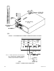
16.Send CAL:ZERO to prepare for current calibration. After sending the command, the BOP out-
put will be set to zero volts. Connect the Kelvin type sense resistor to the BOP output using a
heat sink capable of dissipating 10 times rated power of sense resistor. Connect the DVM to
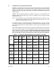
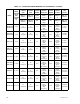
the sensing terminals of the Kelvin type sense resistor as shown in Figure 3-2. Table 3-2 pro-
vides suggested sense resistor values for various BOP current outputs, as well as the for-
mula for calculating expected measured values and tolerances for any sense resistor where
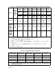
the precise resistance is known. Table 3-3 lists possible sources for obtaining the suggested
sense resistors
17.Set the BOP to zero volts across the sense resistor (corresponding to zero current) under
the low (1/4 Scale) current range by sending CAL:LCURR ZERO. Monitor the DVM con-
nected to the sense resistor and send the command CAL:DPOT 64 to increase the output
voltage and CAL:DPOT -32 to set the digital pot to the center of its range. Adjust A1R83 on
BOP until the DVM reads the voltage specified in Table 3-2 for LOW CURRENT ZERO.
18.Set the BOP current to 0 Amps in current mode by sending CAL:CURR ZERO. Use the com-
mand CAL:DPOT 1 to increase the current or CAL:DPOT -1 to decrease the current until
the DVM reads the voltage specified in Table 3-2 for MAIN CURRENT ZERO.