
Operator Manual User Manual

BIT 4886 120413 2-7
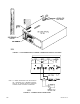
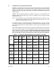
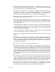
FIGURE 2-4. RJ45 TO DB9 ADAPTER WIRING
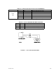
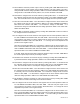
TABLE 2-4. RS232C PORT INPUT/OUTPUT PIN ASSIGNMENTS
CONNECTOR PIN SIGNAL NAME FUNCTION
RS 232
PORT
1 RTS Request To Send (protocol not used)
2RXD Receive Data
3 TXD Transmit Data
4 LOGIC GND Logic Ground
5 LOGIC GND Logic Ground
6 CTS Clear To Send (protocol not used)
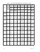
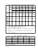
TABLE 2-5. RJ45 TO DB9 ADAPTER WIRE FUNCTIONS
Wire DB9 Pin Purpose
Green 5 Return for pins 2 and 3.
Brown 3 Carries data from the Kepco power supply to the controller.
Yellow 2 Carries data from the controller to the Kepco power supply.