
Operator Manual User Manual


2-6 BIT 4886 120413
2.4 INPUT/OUTPUT SIGNALS
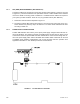
The IEEE 488 port is a 24 pin IEEE 488 connector (Figure 2-3) and conforms mechanically and
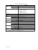
electrically to the IEEE 488 standard; refer to Table 2-3 for pin assignments. Table 2-4 describes
the RS 232 port pin connections.
FIGURE 2-3. IEEE 488 (GPIB) CONNECTOR
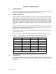
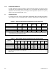
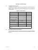
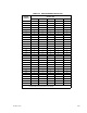
TABLE 2-3. INPUT/OUTPUT PIN ASSIGNMENTS
PIN SIGNAL NAME FUNCTION
1
D
I01
I/O Line
2
D
I02
I/O Line
3
D
I03
I/O Line
4
D
I04
I/O Line
5 EOI End or Identify
6 DAV Data Valid
7 NRFD Not Ready for Data
8 NDAC Not Data Accepted
9 IFC Interface Clear
10 SRQ Service Request
11 ATN Attention
12 SHIELD Shield
13
D
I05
I/O Line
14
DI06
I/O Line
15
DI07
I/O Line
16
DI08
I/O Line
17 REN Remote Enable
18 GND Ground (signal common)
19 GND Ground (signal common)
20 GND Ground (signal common)
21 GND Ground (signal common)
22 GND Ground (signal common)
23 GND Ground (signal common)
24 LOGIC GND Logic Ground