
Manual


BIT 232 022800
3-3
3.6 VOLTAGE READING ZERO CALIBRATION (R35)
1. Program the BOP power supply for ZERO VOLTAGE and MAXIMUM CURRENT LIMIT.
2. ‘MEASURE’ (‘FETCH’ in CIIL syntax) the OUTPUT VOLTAGE of the BOP.
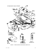
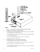
3. Locate VOLTAGE READBACK ZERO control R35 (see Figures 2-1 and 3-1, refer to Table
3-1).
4. Continue to ‘MEASURE’ (‘FETCH’ in CIIL syntax) the VOLTAGE READING while adjusting
control R35 until the ‘MEASUREd’ (‘FETCHed’ in CIIL syntax) value is not 0.0.
5. Continue to ‘MEASURE’ (‘FETCH’ in CIIL syntax) the VOLTAGE READING while adjusting
control R35 until the ‘MEASUREd’ (‘FETCHed’ in CIIL syntax) value is 0.0. Once a stable
value of 0.0 is reached, continue rotating R35 four full (360°) turns in the same direction. Ver-
ify VOLTAGE READING is 0.0.
3.7 VOLTAGE READING CALIBRATION (R19)
1. Program the BOP Power Supply for PLUS FULL SCALE VOLTAGE, less one percent (verify
by reading external DVM).
NOTE: If the unit is calibrated using CIIL syntax, send the ‘GAL’ command followed by
the ‘FØ ’ switch command.
2. ‘MEASURE’ (‘FETCH’ in CIIL syntax) the OUTPUT VOLTAGE of the BOP Power Supply.
3. Locate VOLTAGE READ. CAL. control R19 (see Figures 2-1 and 3-1, refer to Table 3-1).
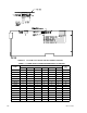
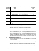
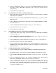
TABLE 3-1. BOP POWER SUPPLY, INTERNAL CALIBRATION CONTROLS
REFERENCE
DESIGNATION
CONTROL
NAME
PURPOSE
ADJUSTMENT
PROCEDURE
(PAR.)
R19 VOLTAGE READING
‘MEASURE’d voltage reading adjustment 3.7
R20 CURRENT READING
‘MEASURE’d current reading adjustment 3.11
R21 VOLTAGE FULL SCALE
Full scale output voltage adjustment 3.5
R22 CURRENT FULL SCALE
Full scale output current adjustment 3.9
R31, R32 ( ± ) 10V CAL.
Reference voltage calibration 3.2
R35 VOLTAGE READBACK ZERO
Aero output voltage adjustment 3.6
R36 CURRENT READBACK ZERO
Zero output current adjustment 3.10
R50 AMMETER ZERO
Sensing amplifier offset adjustment 3.3
R81
E
O
COMP AMP ZERO
Voltage channel zero adjustment
3.4
R83
I
O
COMP AMP ZERO
Current channel zero adjustment
3.8