
Manual


BIT 232 022800
2-5/2-6
2.4 INPUT/OUTPUT SIGNALS
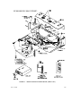
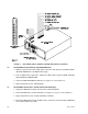
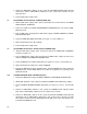
The RS232 port is a standard 9 pin connector (Figure 2-4) conforming to the IBM AT 9-Pin RS
232 Serial Interface. Refer to Table 2-3 for pin assignments.
FIGURE 2-3. RS 232C CONNECTOR
2.5 RS 232 CONNECTIONS
Since the BIT Card uses a 9-pin male connector, it is classified as a Data Terminal Equipment
(DTE) in accordance with the RS 232 Standard (equipment using a female connector is classi-
fied as Data Communication Equipment, DCE).
Either a DTE to DTE or a null modem cable is required to connect the BIT Card to an IBM-PC
compatible computer. This cable connects RXD at one end to TXD at the other end, DTR at one
end to DSR at the other end, and CTS at one end with RTS at the other end
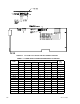
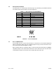
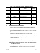
TABLE 2-2. INPUT/OUTPUT PIN ASSIGNMENTS
PIN SIGNAL NAME FUNCTION
1 SGND Signal Ground
2 RXD Receive Data
3 TXD Transmit Data
4 DTR Data Terminal Ready
5 SGND Signal Ground
6 DSR Data Set Ready
7 RTS Request To Send
8 CTS Clear To Send
9 SGND Signal Ground