OPERATOR’S MANUAL BIT 232, BIT 232-F DIGITAL INTERFACE CARD KEPCO INC. MODEL BIT 232, BIT 232-F INTERFACE CARD ORDER NO. REV. NO. IMPORTANT NOTES: 1) This manual is valid for the following Model and associated serial numbers: MODEL SERIAL NO. REV. NO. 2) A Change Page may be included at the end of the manual. All applicable changes and revision number changes are documented with reference to the equipment serial numbers.
TABLE OF CONTENTS SECTION PAGE SECTION 1 - INTRODUCTION 1.1 1.2 1.3 1.4 Scope of Manual ..................................................................................................................................... 1-1 General Description................................................................................................................................. 1-1 Specifications, BIT 232/BIT 232-F.................................................................................................
TABLE OF CONTENTS SECTION PAGE APPENDIX A - SCPI COMMON COMMAND/QUERY DEFINITIONS A.1 Introduction ..............................................................................................................................................A-1 APPENDIX B - SCPI COMMAND/QUERY DEFINITIONS B.1 Introduction ..............................................................................................................................................B-1 APPENDIX C - CIIL COMMAND DEFINITIONS C.
LIST OF FIGURES FIGURE 1-1 2-1 2-2 2-3 3-1 3-2 4-1 4-2 A-1 A-2 A-3 A-4 A-5 A-6 A-7 A-8 A-9 A-10 A-11 A-12 A-13 A-14 B-1 B-2 B-3 B-4 B-5 B-6 B-7 B-8 B-9 B-10 B-11 B-12 B-13 B-14 B-15 B-16 B-17 B-18 B-19 B-20 B-21 B-22 B-23 B-24 C-1 C-2 C-3 C-4 C-5 C-6 C-7 C-8 TITLE PAGE Remotely Controlled Power Supply Configurations Using Kepco Products............................................... vi Installation of BIT Card into BOP .....................................................................................
LIST OF TABLES TABLE 1-1 1-2 1-3 2-1 2-2 3-1 4-1 4-2 A-1 B-1 C-1 C-2 C-3 D-1 E-1 TITLE PAGE Kepco BIT 232, 488 and 4882 Digital Programming Cards ........................................................................1-1 Applicability of BIT Interface Cards to Specific BOP Models ......................................................................1-2 Specifications, BIT 232 and BIT 232-F .......................................................................................................
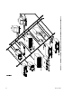
vi BIT 232 022800 FIGURE 1-1.
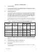
SECTION 1 - INTRODUCTION 1.1 SCOPE OF MANUAL This manual contains instructions for the installation, operation and maintenance of the BIT 232 and BIT 232-F Interface Cards manufactured by Kepco, Inc., Flushing, NY, U.S.A. References to “BIT Card” refer to both models. 1.2 GENERAL DESCRIPTION The Kepco BIT Card Series were designed as an accessory for the Kepco BOP series bipolar power supplies. The BIT cards make it possible to control the BOP output by means of digital input signals (see Figure 1-1).
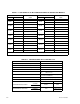
TABLE 1-2. APPLICABILITY OF BIT INTERFACE CARDS TO SPECIFIC BOP MODELS BOP TO BE MODIFIED MODEL APPLICABLE CARD REVISION NO. 1 MODEL BIT 232-F, BIT 4882-F 20-5M APPLICABLE CARD REVISION NO.
SECTION 2 - INSTALLATION 2.1 UNPACKING AND INSPECTION The BIT Card has been thoroughly inspected and tested prior to packing and is ready for operation following installation. Unpack, saving original packing material. If any indication of damage is found, file a claim immediately with the responsible transport service. 2.
NOTE: Step numbers coincide with encircled numbers on Figure 2-1, sheet 2. Step 1. Disconnect a-c power from BOP by removing line cord. Step 2. Remove BOP cover (see Section 5, Figure 5-1 of your BOP Instruction Manual). Step 3. Remove and discard Rear Cover Plate (PN 128-1434) and associated hardware. Step 4. Remove J204 Connector Assembly (PN 241-0680) from Location #1, save for Step 11. Step 5.
FIGURE 2-1. BIT 232 022800 INSTALLATION OF BIT CARD INTO BOP (SHEET 2 OF 2).
FIGURE 2-2. BIT 232/BIT 232-F SWITCH AND ADJUSTMENT LOCATIONS TABLE 2-1.
2.4 INPUT/OUTPUT SIGNALS The RS232 port is a standard 9 pin connector (Figure 2-4) conforming to the IBM AT 9-Pin RS 232 Serial Interface. Refer to Table 2-3 for pin assignments. TABLE 2-2. INPUT/OUTPUT PIN ASSIGNMENTS PIN SIGNAL NAME 1 SGND Signal Ground 2 RXD Receive Data 3 TXD Transmit Data 4 DTR Data Terminal Ready 5 SGND Signal Ground 6 DSR Data Set Ready 7 RTS Request To Send 8 CTS Clear To Send 9 SGND Signal Ground FIGURE 2-3. 2.
SECTION 3 - CALIBRATION NOTE: The calibration procedures below are for the purpose of recalibration and for the case where the BIT card is installed by the user. Unless otherwise noted, syntax is in SCPI. 3.1 EQUIPMENT REQUIRED The following is a listing of equipment required for calibration of the BIT Card installed in a Kepco “BOP” Series Power Supply: A. Precision digital voltmeter (DVM), 5 digit minimum resolution (suggested). B.
FIGURE 3-1. 3.4 BOP POWER SUPPLY, INTERNAL CALIBRATION CONTROL LOCATIONS ADJUSTMENT OF THE OUTPUT VOLTAGE ZERO (R81) 1. Without a load connected to the BOP output, connect a DVM between the FRONT PANEL SENSING TERMINALS of the BOP Power Supply. 2. Turn the BOP Power Supply “ON”, program the BOP Power Supply to ZERO VOLTAGE AND MAXIMUM CURRENT LIMIT. 3. Locate Eo COMP AMP ZERO control R81 (see Figure 3-1, refer to Table 3-1). 4. Adjust control R81 for zero, ±100 microvolts. 3.
TABLE 3-1. BOP POWER SUPPLY, INTERNAL CALIBRATION CONTROLS ADJUSTMENT PROCEDURE (PAR.) REFERENCE DESIGNATION CONTROL NAME R19 VOLTAGE READING ‘MEASURE’d voltage reading adjustment 3.7 R20 CURRENT READING ‘MEASURE’d current reading adjustment 3.11 R21 VOLTAGE FULL SCALE Full scale output voltage adjustment 3.5 R22 CURRENT FULL SCALE Full scale output current adjustment 3.9 R31, R32 ( ± ) 10V CAL. Reference voltage calibration 3.
4. Continue to ‘MEASURE’ (‘FETCH’ in CIIL syntax) the VOLTAGE READING while adjusting control R19, until the ‘MEASUREd’ (‘FETCHed’ in CIIL syntax) value matches the programmed value. 5. Turn the BOP Power Supply “OFF”. 3.8 ADJUSTMENT OF THE OUTPUT CURRENT ZERO (R83) 1. With the BOP Power Supply “OFF”, connect a precision current shunt between the FRONT PANEL OUTPUT TERMINALS. 2. Connect the DVM to the REAR PROGRAMMING CONNECTOR (PC 12); between COMMON and pin 10. 3.
FIGURE 3-2. 3.11 CURRENT SHUNT CONNECTIONS CURRENT READING CALIBRATION (R20) 1. Program the BOP Power Supply for PLUS FULL SCALE CURRENT, less one percent (verify by reading external DVM). NOTE: If the unit is calibrated using CIIL syntax, send the ‘GAL’ command followed by the ‘FØ ’ switch command. 2. ‘MEASURE’ (‘FETCH’ in CIIL syntax) the OUTPUT CURRENT of the BOP Power Supply. 3. Locate CURRENT READ. CAL. control R20 (see Figures 2-1 and 3-1, refer to Table 3-1). 4.
SECTION 4 - OPERATION 4.1 GENERAL The Kepco BOP Power Supply, with an installed BIT 232/BIT 232-F Interface Card, may be programmed over the RS232C bus using either SCPI (Standard Commands for Programmable Instruments) or CIIL (Control Interface Intermediate Language) commands. SCPI and CIIL provide a common language used in an automatic test system. (Refer to Table 2-3 for input/output signal allocations.) 4.
Sample programs provided in Appendices D through G guide the user in setting up a program to communicate with the BOP via the BIT 232/BIT 232-F Interface Card. 4.4 SCPI PROGRAMMING SCPI (Standard Commands for Programmable Instruments) is a programming language conforming to the protocols and standards established by IEEE 488.2 (reference document ANSI/ IEEE Std 488.2, IEEE Standard Codes, Formats, Protocols, and Common Commands).
ROOT : (colon) INITiate [:IMMediate] :CONTinuous MEASure :CURRent? :VOLTage? [SOURce:] VOLTage [:LEVel] [:IMMediate] :TRIGgered CURRent [:LEVel] [:IMMediate] :TRIGgered FUNCtion :MODE FIGURE 4-1. 4.4.
TABLE 4-1.
KEYWORD DATA SEPARATOR ROOT SPECIFIER DATA MESSAGE UNIT SEPARATOR MESSAGE UNIT SEPARATOR DATA DATA SEPARATOR ROOT SPECIFIER KEYWORD KEYWORD KEYWORD SEPARATOR QUERY INDICATOR MESSAGE TERMINATOR KEYWORD CURR:LEV 3.5;:OUTP ON;:CURR? MESSAGE UNIT FIGURE 4-2. MESSAGE STRUCTURE You must use the rules above when using keywords. Using an arbitrary short form such as ENABL for ENAB (ENABLE) or IMME for IMM (IMMEDIATE) will result in an error.
4.4.4.4 DATA Some commands require data to accompany the keyword either in the form of a numeric value or character string. Data always follows the last keyword of a command or query (e.g., VOLT:LEV:TRIG 14 or SOUR:VOLT? MAX 4.4.4.5 DATA SEPARATOR Data must be separated from the last keyword by a space (e.g., VOLT:LEV:TRIG 14 or SOUR:VOLT? MAX 4.4.4.6 MESSAGE UNIT SEPARATOR When two or more message units are combined in a program message, they must be separated by a semicolon (;) (e.g.
Optional keywords are enclosed in brackets [ ] for identification; optional keywords can be omitted and the power supply will respond as if they were included in the message. The root level keyword [SOURce] is an optional keyword. Starting at the root, there are various branches or paths corresponding to the subsystems. The root keywords for the BIT Card are :INITiate, :MEASure, :OUTPut, [:SOURce], :STATus, and :SYSTem.
4.5 • Commands/queries may be given in upper/lower case (long form) e.g., SoUrCe is allowed. • Text shown between brackets [] is optional. e.g., :[SOUR]VOLT:[LEV] TRIG has the same effect as :VOLT TRIG CIIL PROGRAMMING The CIIL command language is used on early models of Kepco power supplies and controllers. The command functions are included here for compatibility with other equipment programmed with CIIL commands. The CIIL command set for the BIT Card is defined and explained in Appendix C. 4.
APPENDIX A - SCPI COMMON COMMAND/QUERY DEFINITIONS A.1 INTRODUCTION This appendix defines the SCPI common commands and queries used with the BIT 232/BIT 232-F Interface Card. Common commands and queries are preceded by an asterisk (*) and are defined and explained in Figures A-1 through A-14, arranged in alphabetical order. Table A-1 provides a quick reference of all SCPI common commands and queries used in the BIT Card. TABLE A-1.
*ESE Syntax: *ESE = positive whole number: 0 to 255 per STANDARD EVENT STATUS ENABLE REGISTER BITS table below. Function: Sets ESE (standard Event Status Enable) register bits to enable the Standard events to be summarized in the Status Byte register (1 = set = enable function, 0 = reset = disable function).
*ESR? Syntax: *ESR? Response: value per STANDARD EVENT STATUS REGISTER BITS table below. Function: This query reads the Standard Event Status Event register, clearing the register at the same time.
*OPC Syntax: *OPC Function: Causes power supply to set status bit 0 (Operation Complete) when pending operations are complete Description: This command sets Standard Event Status Register bit 0 to “1” when all previous commands have been executed and changes in output level have been completed. This command does not prevent processing of subsequent commands, but bit 0 will not be set until all pending operations are completed.
*RST Syntax: *RST Function: Resets power supply as defined below: Response: None Description: Establishes the following power supply parameters: CURR[:LEV][:IMM] VOLT[:LEV][:IMM] FUNC:MODE Example: *RST 0 0 VOLT Power supply responds by establishing default states defined above. FIGURE A-8.
*SRE Syntax: *SRE = value from 0 - 255 per SERVICE REQUEST ENABLE REGISTER table below, except bit 6 cannot be programmed.
*STB? Syntax: *STB? Response: value from 0 to 255 per table below Function: Read Status Byte Register without clearing it Description: This Query reads the Status Byte Register (bit 6 = MSS) without clearing it (1 = set = function enabled, 0 = reset = function disabled). The register is cleared only when subsequent action clears all set bits. MSS is set when the power supply has one ore more reasons for requesting service.
*TST? Syntax: *TST? Response: 0 1 Function: Power Supply test Description: This query causes the power supply to do a self-test and provide the controller with pass/fail results. = pass test = fail test CAUTION: TO AVOID DAMAGE TO THE LOAD, DISCONNECT THE LOAD BEFORE ISSUING THIS COMMAND. (DURING THE SELF-TEST, THE BOP IS PROGRAMMED TO FULL SCALE POSITIVE AND FULL SCALE NEGATIVE OUTPUT.
APPENDIX B - SCPI COMMAND/QUERY DEFINITIONS B.1 INTRODUCTION This appendix defines the SCPI subsystem commands and queries used with the BIT 232/BIT 232-F Interface Card. Subsystem commands are defined in Figures B-1 through B-26, arranged in groups as they appear in the tree diagram, Figure 3-3. Table B-1 provides a quick reference of all SCPI subsystem commands and queries used in the BIT Card. TABLE B-1.
INIT:CONT Syntax: Short Form: Long Form: Function: INIT:CONT ON Enables continuous triggers. INIT:CONT OFFDisables continuous triggers. Description: This command enables/disables triggers. *TRG commands complete the sequence. Once INIT:CONT ON enables continuous triggers, subsequent *TRG commands return the power supply output to the commanded values of voltage and current established by the VOLT:TRIG and CURR:TRIG commands until INIT:CONT OFF is received.
MEAS:CURR? MEAS:VOLT? Syntax: Short Form: : Long Form: Function: Measures actual current or voltage Description: This query returns the actual value of output current or voltage (measured at the sense terminals) as determined by the commanded value of voltage and current and load conditions. Example: VOLT 21; CURR 5 MEAS:CURR? MEAS:VOLT? MEAS:CURR? MEAS:VOLT? MEASure:CURRent[:DC]? MEASure:VOLTage[:DC]? FIGURE B-4.
CURR Syntax: Short Form: Long Form: Function: Sets commanded current or current limit to specified level. Description: This command programs output current (Current mode) or current limit (Voltage mode) to a specific value. Actual output current will depend on load conditions. Example: VOLT 21; CURR 5 CURR [SOURce]:CURRent[:LEVel][:IMMediate] Power supply output commanded to go to 21V, 5A FIGURE B-5.
CURR:TRIG Syntax: Short Form: Long Form: Function: Programs current value to be implemented by *TRG command. Actual output current will depend on load conditions. Description: This command can be used to reset many power supplies to preselected parameters by issuing a single *TRG command. Example: VOLT 21; CURR 1.1 CURR:TRIG 2.3 CURR? *TRG CURR:TRIG [SOURce]:CURRent:TRIGgered CURR? Power supply commanded to go to 21V, 1.1A Power supply current programmed to 2.
VOLT Syntax: Short Form: Long Form: Function: Sets commanded voltage or voltage limit to specified level. Description: This command programs commanded output voltage (Voltage mode) or voltage limit (Current mode) to a specific value. Actual output voltage will depend on load conditions. Example: VOLT 21; CURR 5 VOLT [SOURce]:VOLTage[:LEVel][:IMMediate] Power supply commanded to go to 21V, 5A FIGURE B-9.
VOLT:TRIG Syntax: Short Form: Long Form: Function: Programs voltage value to be implemented by *TRG command. Actual output voltage will depend on load conditions. Description: This command can be used to reset many power supplies to preselected parameters by issuing a single *TRG command. Example: VOLT 21; CURR 1.1 VOLT:TRIG 29.3 VOLT? *TRG VOLT:TRIG [SOURce]:VOLTage:TRIGgered VOLT? Power supply commanded to go to 21V, 1.1A Power supply current programmed to 29.
FUNC:MODE Syntax: Short Form: Long Form: Function: FUNC:MODE VOLT FUNC:MODE CURR Description: Commanded mode establishes parameters (voltage or current) monitored for error conditions. Actual mode depends upon load conditions. When commanded to Voltage mode, if load conditions cause the power supply to try to exceed the current limit, the unit will automatically switch to Current mode and flag an error condition.
STAT:OPER:ENAB Syntax: Short Form: Long Form: Function: Programs Operational Condition Enable Register) Description: The Operation Condition Enable Register determines which conditions are allowed to set the Operation Condition Register. The value sent by the controller sets the corresponding bits of the Operation Condition Enable Register in the power supply (1 = set = function enabled, 0 = reset = function disabled).
STAT:OPER? Syntax: Short Form: Long Form: Function: Indicates changes in conditions monitored by Operational Event Register) Description: Power supply returns value to controller indicating conditions of Operation Event Register which have changed since the last STAT:OPER? query. This value is cleared once reported...
STAT:QUES? Syntax: Short Form: Long Form: Function: Indicates changes in conditions monitored by Questionable Event Register) Description: Power supply returns value to controller indicating conditions of Questionable Event Register which have changed since the last STAT:OPER? query. This value is cleared once reported.
STAT:QUES:ENAB Syntax: Short Form: Long Form: Function: Programs Questionable Condition Enable Register) Description: The Questionable Condition Enable Register determines which conditions are allowed to set the Questionable Condition Register. The value sent by the controller sets the corresponding bits of the Questionable Condition Enable Register in the power supply (1 = set = function enabled, 0 = reset = function disabled.
SYST:ERR? Syntax: Short Form: Long Form: Function: Provides error messages to controller. Description: Returns error number and character string containing error message. Error messages are defined as follows: SYST:ERR? SYSTem:ERRor? ERROR MESSAGES ERROR MESSAGE EXPLANATION No error 0 “No error” -100 “Command error” Wrong syntax; command not understood.
APPENDIX C - CIIL COMMAND DEFINITIONS C.1 INTRODUCTION This appendix defines the CIIL commands used with the BIT 232/BIT 232-F Interface Card. Table C-1 provides a quick reference of all CIIL commands used in the BIT Card. TABLE C-1.
INX Syntax: INX VOLT (initiate voltage reading) INX CURR (initiate current reading) Function: Commences a data acquisition process in accordance with the preceding FNC command. Description: The response to the INX command is a dynamic time-out value, unless a catastrophic error condition exists, in which case an error message will be returned. If the time-out value returned is not zero, this indicates the power supply’s output voltage or current has not yet settled.
SET, SRX, SRN Syntax: FNC DCS :CH1 SET VOLT CURL FNC DCS :CH1 SET CURR VLTL SRX Set Range Maximum SRN Set Range Minimum Function: This operator is used in conjunction with FNC (in stimulus mode) to specify the output mode of the power supply being programmed. Description: The first operand is the noun modifier and the second operand specifies the value. The first operand field of the command contains the four(4) letter mnemonic for the output mode of the power supply.
RST Syntax: RST DCS :CH1 Function: This operator is used to return a power supply to its power-on state. The output voltage and current are programmed to zero. Example: RST DCS :CH1 The power supply is reset. FIGURE C-5. RST — RESET COMMAND CNF, IST Syntax: CNF or IST Function: Causes power supply to execute confidence test.
STA Syntax: STA Function: Causes power supply to return operating status to controller. Description: This operator commands the power supply to report its present operating status. Status is reported in the form of a message (character string) as defined below. Any catastrophic error conditions (indicated by * in the table below) which exist will be reported, until the error condition is corrected.
GAL Syntax: GAL Function: Enables utility commands which change error handling defaults. Description: This command enables the utility commands listed below. If no GAL command is issued, the default conditions are T0, F1, and P1. Once the GAL command is issued, the appropriate utility command may be sent to change the default condition. TABLE C-3.
APPENDIX D - TERMINAL EMULATION PROGRAM D.1 INTRODUCTION Appendix D is a C language program used with an IBM-PC-compatible computer as a terminal emulator, allowing the BOP to be controlled directly from a keyboard. Refer to Appendix F for all functions. (See PAR. 1.4 to order Sample Programs diskette.) To modify this program for computers other than IBM-PC-compatible (e.g., Macintosh), four ROM BIOS routines must be replaced with their equivalent (see Table D-1). TABLE D-1.
/******************************************************************** * RS232 interactive driver for BIT232 * use ROM BIOS INT 14 function calls ********************************************************************/ #include #include #include
APPENDIX E - RS232 COMMAND LOOP PROGRAM E.1 INTRODUCTION This appendix is a C language program used with an IBM-PC-compatible computer running a terminal emulation program to set up a command loop. Refer to Appendix F for all function prototypes. (See PAR. 1.4 to order Sample Programs diskette.) To modify this program for computers other that IBM-PC-compatible (e.g., Macintosh), four ROM BIOS routines must be replaced with their equivalent (see Table E-1). TABLE E-1.
/******************************************************************** * RS232 command loop program for BIT232 * use ROM BIOS INT 14 function calls ********************************************************************/ #include #include #include
{ if (string[j] == ‘\r’) string[j] = ‘\0’; } /* get maximum voltage */ strcpy(string, “volt?max”); SendCmmdWready(string); /* change the first \r in end of string */ for (j = 0; j < strlen(string); j++) { if (string[j] == ‘\r’) string[j] = ‘\0’; } max = atof(string); if (max <= 10.0) vl=1; else { if (max <= 100.0) vl=2; else vl=3; } j=0; volt[0]=string[j]; volt[1]=’\0’; j ++; if (vl > 1) if( string[j] == ‘.
c = getch(); if (c == 0) /* exit on Alt-Q */ if (getch() == 16) exit(0); } strcpy(wstr,string); /* set voltage to full scale, current 0.5A */ SendCmmdWready(wstr); for (j = 0; j < 10000; j++) for (k = 0; k < 100; k++); strcpy(wstr,msvolt); /* read voltage and current */ SendCmmdWready(wstr); for (j = 0; j < 10000; j++); strcpy(wstr,stringm); /* set voltage to minus full scale, current 0.
APPENDIX F - C LANGUAGE FUNCTIONS F.1 INTRODUCTION This appendix contains examples of C language functions which can be used as the building blocks for unique programs to interface the BIT Card and associated power supply with an IBMPC-compatible computer. These functions are used in the sample programs shown in Appendices D and E. F.
F.4 SEND, WAIT FOR ECHO This function sends a character to the serial port specified by (n), allows a small delay (about 50 msec) for the character to be received by the BIT card, analyzed, put in a buffer and echoed back. If the BIT Card did not receive the character, or if the time-out expires, the BIT card returns the EOF character. This command could be modified so that if the time-out expires, the last character is sent to the BIT Card again.
F.6 CHECK TO SEE IF A CHARACTER WAS RECEIVED This function checks to see if a character was received using the ROM BIOS routine; if the computer is not IBM-PC-compatible the ROM BIOS routine must be replaced by an equivalent. /* check to see if a character was received */ int in_ready(int n) { union REGS regs; /* AH has the function code */ regs.h.ah = 0x03; /* DX has the port number */ if (n == 1) regs.x.dx = 0; else regs.x.
F.8 SEND COMMAND AND WAIT UNTIL READY This function uses the SendCommand function to send commands to the BIT Card and display echoed characters and response messages on the screen until the > character is received, indicating that parsing and execution of the command has been completed.
APPENDIX G - BASIC LANGUAGE TERMINAL EMULATION G.1 INTRODUCTION This appendix presents a program written in BASIC language intended to aid the user in building BASIC language test programs using the BIT Card. (See PAR. 1.4 to order Sample Programs diskette.) The BASIC Language Terminal Emulation program performs a series of commands, then allows the user to type commands and control a BOP via the BIT Card from a keyboard.
VIEW PRINT 1 TO 23 ‘ Print between lines 1 & 23.
‘ ========================= FILTER ========================== ‘ Filters characters in an input string.
‘ ========================= Send Command ===================== ‘ Send command line using SendWecho ‘ ============================================================ ‘ SUB SendCommand (SendCmmd$) STATIC FOR K = 1 TO LEN(SendCmmd$) Istr$ = MID$(SendCmmd$, K, 1) SendWecho Istr$ PRINT Istr$; ‘ then print.