
Instruction Manual

BHK-MG (OPR) 022014 2-5
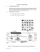
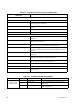
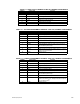
TABLE 2-6. REAR OUTPUT TERMINAL STRIP TB1 TERMINAL ASSIGNMENTS
TERMINAL SIGNAL NAME FUNCTION
1 +S Positive sense connection
2 + OUT Positive d-c output connection
3 GND NET Grounding network connection
4 GND Ground (chassis) connection
5 – OUT Negative d-c output connection
6 –S Negative sense connection
7 – OUT C Connection to internal output capacitor
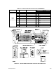
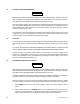
TABLE 2-7. VOLTAGE PROGRAMMING TERMINAL STRIP TB2, TERMINAL ASSIGNMENTS
TERMINAL SIGNAL NAME FUNCTION
1 –10V –10V d-c reference voltage
2 V(NINV) Noninverting input of uncommitted amplifier
3 SGND Signal common
4 V(+IN) Programming input for positive input signal
5 +10V +10V d-c reference voltage
6 V(INV) Inverting input of uncommitted amplifier
7 V(FBK) Internal feedback resistor; the other end is connected to
uncommitted amplifier output
8 V(OUT) Output of uncommitted amplifier
9 –V EXT External analog programming voltage input: 0 to –10V pro-
grams 0 to 100% of E
O
max.
10 SGND Signal common
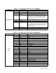
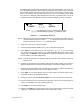
TABLE 2-8. CURRENT PROGRAMMING TERMINAL STRIP TB3, TERMINAL ASSIGNMENTS
TERMINAL SIGNAL NAME FUNCTION
1 –10V –10V d-c reference voltage
2 C(NINV) Noninverting input of uncommitted amplifier
3 SGND Signal common
4 C(+IN) Programming input for positive input signal
5 +10V +10V d-c reference voltage
6 C(INV) Inverting input of uncommitted amplifier
7 C(FBK) Internal feedback resistor; the other end is connected to
uncommitted amplifier output
8 C(OUT) Output of uncommitted amplifier
9 C EXT External analog programming voltage input: 0 to –10V pro-
grams 0 to 100% of I
O
max. Usually connected to output of
uncommitted amplifier.
10 SGND Signal common