
Instruction Manual
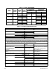
LIST OF FIGURES
FIGURE TITLE PAGE
BHK 500-0.4MG SVC 022014
vii
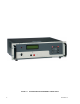
1-1 BHK-MG Series Programmable Power Supply.............................................................................................. x
1-2 BHK Series Power Supply, Mechanical Outline Drawing............................................................................ 1-6
2-1 BHK-MG Series, Front Panel Controls, Indicators and Connectors............................................................ 2-1
2-2 BHK-MG Series, Rear Panel Controls and Connections ............................................................................ 2-3
2-3 LCD Power On Defaults.............................................................................................................................. 2-7
2-4 Local Sensing, Slow Mode Selected, Grounding Network Connected,
Floating Output (Factory Default Configuration)....................................................................................... 2-12
2-5 Remote Sensing, Fast Mode Selected, Positive Output Grounded ............................................................ 2-12
2-6 Status Port Opto-coupler Active “High” Configuration................................................................................. 2-13
2-7 Status Port Opto-coupler Active “Low” Configuration ................................................................................. 2-13
3-1 LCD Power On Defaults.............................................................................................................................. 3-5
3-2 Programming Example to Verify Previous Command has Completed........................................................ 3-20
3-3 RS 232 Implementation .............................................................................................................................. 3-22
3-4 Message Structure...................................................................................................................................... 3-27
3-5 Tree Diagram of SCPI Commands Used with BHK-MG Power Supply ...................................................... 3-28
3-6 Typical Example Of BHK-MG Power Supply Program Using SCPI Commands......................................... 3-31
3-7 Analog Voltage Programming, Simplified Diagram..................................................................................... 3-32
3-8 Analog Current Programming, Simplified Diagram ..................................................................................... 3-32
3-9 Analog Programming of Output Voltage (Voltage Mode)
or Voltage Limit (Current Mode) using Resistance.................................................................................. 3-35
3-10 Analog Programming of Output Current (Current Mode)
or Current Limit (Voltage Mode) using Resistance.................................................................................. 3-36
3-11 Analog Programming of Output Voltage (Voltage Mode) or Voltage Limit
(Current Mode) using Isolated (floating) Low Impedance Voltage Source (VS)...................................... 3-38
3-12 Analog Programming of Output Voltage (Voltage Mode) or Voltage
Limit (Current Mode) using Grounded Low Impedance Voltage Source (VS)......................................... 3-39
3-13 Analog Programming of Output Current (Current Mode) or Current Limit
(Voltage Mode) using Isolated (Floating) Low Impedance Voltage Source (VS) .................................... 3-40
3-14 Analog Programming of Output Current (Current Mode) or Current
Limit (Voltage Mode) using Grounded Low Impedance Voltage Source (VS) ........................................ 3-41
3-15 Analog Programming of Output Voltage (Voltage Mode) or Voltage
Limit (Current Mode) using High Impedance, Low Level (1V) Voltage Source (VS)............................... 3-44
3-16 Analog Programming of Output Current (Current Mode) or Current
Limit (Voltage Mode) using High Impedance, Low Level (1V) Voltage Source (VS)............................... 3-45
3-17 Analog Programming of Output Voltage (Voltage Mode) or Voltage
Limit (Current Mode) using Current Source (1mA) (CS) ......................................................................... 3-47
3-18 Analog Programming of Output Current (Current Mode) or Current
Limit (Voltage Mode) using Current Source (1mA) (CS) ......................................................................... 3-48
3-19 Slow Mode/Fast Mode Operation ............................................................................................................... 3-51
3-20 Series Automatic Configuration .................................................................................................................. 3-55
3-21 Series Master-Slave (Voltage Mode) Configuration.................................................................................... 3-58
3-22 Series Master-Slave (Current Mode) Configuration .................................................................................... 3-59
3-23 Parallel Automatic Configuration................................................................................................................. 3-63
3-24 Parallel Master-Slave (Voltage Mode) Configuration.................................................................................. 3-65
3-25 Parallel Master-Slave (Current Mode) Configuration .................................................................................. 3-68
4-1 GPIB Setup Window ................................................................................................................................... 4-5
4-2 Main Panel (BHK 500-0.4MG, Typical)....................................................................................................... 4-6
4-3 Calibration Panel......................................................................................................................................... 4-6
A-1 GPIB Commands ....................................................................................................................................... A-3
B-1 Programming the Output............................................................................................................................ B-3
B-2 Using Display Commands.......................................................................................................................... B-3
B-3 Using LIST Commands and Queries ......................................................................................................... B-8
B-4 Programming Current ................................................................................................................................ B-12
B-5 Programming Voltage ................................................................................................................................ B-14
B-6 Using Status Commands and Queries....................................................................................................... B-15
B-7 Using System Commands and Queries..................................................................................................... B-19