OPERATOR’S MANUAL BHK-MG FULL RACK SERIES POWER SUPPLY VOLTAGE/CURRENT-STABILIZED DC SOURCE MODELS KEPCO INC. An ISO 9001 Company. BHK 300-0.6MG BHK 500-0.4MG BHK 1000-0.2MG BHK 2000-0.1MG IMPORTANT NOTES: 1) This manual is valid for the following Model and associated serial numbers: MODEL SERIAL NO. REV. NO. 2) A Change Page may be included at the end of the manual. All applicable changes and revision number changes are documented with reference to the equipment serial numbers.
Declaration of Conformity Application of Council directives: 73/23/EEC (LVD) 93/68/EEC (CE mark) Standard to which Conformity is declared: EN61010-1:2001 (Safety requirements for electrical equipment for measurement, control and laboratory use - Part 1) Manufacturer's Name and Address: KEPCO INC. 131-38 SANFORD AVENUE FLUSHING, N.Y. 11355 USA Importer's Name and Address: OPY C E V I T A T N REPRESE Type of Equipment: Component Power Supply Model No.
Conditions of Conformance When this product is used in applications governed by the requirements of the EEC, the following restrictions and conditions apply: 1. For European applications, requiring compliance to the Low Voltage Directive, 73/23/EEC, this power supply is considered a component product, designed for “built in“ applications.
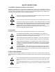
SAFETY INSTRUCTIONS 1. Installation, Operation and Service Precautions This product is designed for use in accordance with EN 61010-1 and UL 3101 for Installation Category 2, Pollution Degree 2. Hazardous voltages are present within this product during normal operation.
TABLE OF CONTENTS SECTION PAGE SECTION 1 - INTRODUCTION 1.1 1.2 1.3 1.4 1.4.1 1.4.2 1.4.2.1 1.4.2.2 1.4.2.3 1.4.3 1.4.4 1.4.5 1.4.6 1.4.7 1.4.8 1.4.9 1.4.10 1.4.11 1.4.12 1.5 1.6 1.7 Scope of Manual ..................................................................................................................................... 1-1 General Description................................................................................................................................. 1-1 Specifications ....
TABLE OF CONTENTS SECTION PAGE 3.2.2 Turning the Power Supply On........................................................................................................... 3-4 3.2.3 Error Conditions ................................................................................................................................ 3-5 3.2.4 Setting Local Mode ........................................................................................................................... 3-5 3.2.
TABLE OF CONTENTS SECTION PAGE 3.5.3.7 STATus Subsystem ..................................................................................................................... 3-25 3.5.3.8 System Subsystem ...................................................................................................................... 3-25 3.5.3.9 TRIGger subsystem ..................................................................................................................... 3-25 3.5.3.
TABLE OF CONTENTS SECTION 4.4.3 4.5 4.6 4.7 4.8 PAGE Calibration Procedure ....................................................................................................................... Changing the Calibration Password ....................................................................................................... Restoring Previous Calibration Values ................................................................................................... Restoring Factory Calibration Values .
TABLE OF CONTENTS SECTION B.30 B.31 B.32 B.33 B.34 B.35 B.36 B.37 B.38 B.39 B.40 B.41 B.42 B.43 B.44 B.45 B.46 B.47 B.48 B.49 B.50 B.51 B.52 B.53 B.54 B.55 B.56 B.57 B.58 B.59 B.60 B.61 B.62 B.63 B.64 B.65 B.66 B.67 B.68 B.69 B.70 B.71 B.72 B.73 B.74 B.75 B.76 B.77 B.78 B.79 B.80 B.81 B.82 PAGE [SOURce:]LIST:QUERy? Query............................................................................................................. [SOURce:]LIST:VOLTage Command................................................
TABLE OF CONTENTS SECTION B.83 B.84 B.85 B.86 B.87 B.88 B.89 B.90 B.91 B.92 vi PAGE SYSTem:ERRor:CODE:ALL? Query ...................................................................................................... SYSTem:KLOCk Command ................................................................................................................... SYSTem:KLOCk? Query ........................................................................................................................
LIST OF FIGURES FIGURE 1-1 1-2 2-1 2-2 2-3 2-4 2-5 2-6 2-7 3-1 3-2 3-3 3-4 3-5 3-6 3-7 3-8 3-9 3-10 3-11 3-12 3-13 3-14 3-15 3-16 3-17 3-18 3-19 3-20 3-21 3-22 3-23 3-24 3-25 4-1 4-2 4-3 A-1 B-1 B-2 B-3 B-4 B-5 B-6 B-7 TITLE PAGE BHK-MG Series Programmable Power Supply.............................................................................................. x BHK Series Power Supply, Mechanical Outline Drawing............................................................................
LIST OF TABLES TABLE 1-1 1-2 1-3 1-4 1-5 1-6 2-1 2-2 2-3 2-4 2-5 2-7 2-8 2-6 2-9 3-1 3-2 3-3 3-4 3-5 3-6 3-7 3-8 3-9 3-10 4-1 4-2 4-3 A-1 A-2 A-3 B-1 B-2 B-3 B-4 viii TITLE PAGE Model Parameters ...................................................................................................................................... 1-2 BHK-MG 200W Specifications ...................................................................................................................
SERVICE SAFETY INSTRUCTIONS Read these safety instructions, as well as the applicable installation, operating and servicing instructions contained in this manual before using the power supply. WARNING Do not touch the output terminals. The high voltage output is dangerous. Electric shock can cause injury or death. Do not remove the cover or disassemble the unit. There are no operator serviceable components or adjustments inside the unit.
FIGURE 1-1.
SECTION 1 - INTRODUCTION 1.1 SCOPE OF MANUAL This manual contains instructions for the installation and operation of the BHK-MG series of 200W output power stabilized voltage or current, d-c power supplies manufactured by KEPCO, Inc., Flushing, New York, U.S.A. WARNING DANGEROUS AND LETHAL POTENTIALS ARE PRESENT, BOTH WITHIN THIS POWER SUPPLY, AND AT THE OUTPUT! Before proceeding to use the power supply, read this manual very carefully.
TABLE 1-1. MODEL PARAMETERS OUTPUT VOLTAGE RANGE (VOLTS) MODEL NUMBER BHK 300-0.6MG 0 - 300 BHK 500-0.4MG 0 - 500 BHK 1000-0.2MG 0 - 1000 BHK 2000-0.1MG 0 - 2000 OUTPUT CURRENT RANGE (mA) MAXIMUM OUTPUT POWER (WATTS) 0 - 600 180 0 - 60 18 0 - 400 200 0 - 40 20 0 - 200 200 0 - 20 20 0 - 100 200 0 - 10 20 OUTPUT EQUIVALENT IMPEDANCE (FAST MODE) VOLTAGE MODE (SERIES R–L) Rd-c (Ohms) L (mH) 0.025 2.0 0.0625 3.6 0.25 6.0 1.
TABLE 1-2. BHK-MG 200W SPECIFICATIONS (Continued) SPECIFICATION RATING/DESCRIPTION CONDITION OUTPUT CHARACTERISTICS (CONTINUED) Temperature effect (per degree C) Voltage 0.01% EO max Current 0.02% IO max Voltage 0.01% EO max Time effect Current 0.02% IO max Ripple (rms/p-p) Voltage: Fast Mode 0.002% / 0.02% EO max Slow Mode 0.001% / 0.01% EO max Ambient temperature 0 to 50° C 0.5-8.5 hours Ambient temperature: 25° C Minus output terminal connected to GND.
TABLE 1-2. BHK-MG 200W SPECIFICATIONS (Continued) SPECIFICATION RATING/DESCRIPTION CONDITION OUTPUT CHARACTERISTICS (CONTINUED) Withstand voltage (All models) 1350V a-c/1 min BHK 300-0.6MG 1950V d-c/1 min Between shorted inputs and chassis Between shorted outputs and chassis. BHK 500-0.4MG 2250V d-c/1 min BHK 1000-0.2MG BHK 2000-0.1MG 2800V d-c/1 min Chassis connection to ground resistance 100 mohms max.
TABLE 1-2.
FIGURE 1-2.
FIGURE 1-2.
1.4 FEATURES 1.4.1 LOCAL CONTROL Front panel keypad entries and an LCD type display are utilized for setting and/or adjusting output voltage and current under local control. The keypad's keys are organized to either directly execute commands, or to introduce a program that can either be run once or cycled. Calibration of the unit is facilitated by a password -protected, menu-driven procedure from the front panel. Refer to PAR. 3.2 for more information. 1.4.
1.4.4 OVERVOLTAGE/OVERCURRENT PROTECTION Overvoltage and Overcurrent protection values can be individually programmed. The range for overvoltage and overcurrent values are 0 to 1.1 x EOmax, 0 to 1.1 x IOmax.
to a dynamically changing load. The fast mode offers a faster response to step or dynamic programming of the output voltage (in voltage mode), when the power supply is used as a power amplifier. Fast mode is also recommended for current stabilization because of its fast response to a dynamically changing load. Refer to PAR. 3.7.1 for more information. 1.4.
h. Current Limit. The current through the main branch of the pass element is monitored. If this current is maintained between 1.8 to 2.2 times larger than the nominal value for more than 11ms, the pass element is latched off, the output capacitor is discharged, and the POWER circuit breaker is tripped to OFF. 1.4.11 CURRENT SINK CAPABILITY BHK-MG 200W Series power supplies are able to sink up to 5% of the nominal current when in voltage mode and 50% of the unit's maximum rated current when in current mode.
1.4.12 ANALOG READBACK AND FLAG SIGNALS AVAILABLE FOR CUSTOMER USE Some internal signals produced by the unit are available at connector A2J5 for either monitoring or testing purposes. Refer to Table 1-3 for a description of available signals TABLE 1-3. CONNECTOR A2J5 SIGNAL DESCRIPTIONS SIGNAL PIN. NO. VALUE TYPE Current Scale Flag 1 ≈ 0V for HIGH current scale > +13V for LOW current scale Collector of PNP transistor (A2Q3) through 1K resistance.
1.6 ACCESSORIES Accessories for the BHK Power Supply are listed in Table 1-5. TABLE 1-5. ACCESSORIES ITEM FUNCTION PART NUMBER IEEE 488 (GPIB) Cable, 1m long Connect BHK-MG Power Supply to GPIB bus. SNC 488-1 IEEE 488 (GPIB) Cable, 2m long Connect BHK-MG Power Supply to GPIB bus. SNC 488-2 IEEE 488 (GPIB) Cable, 4m long Connect BHK-MG Power Supply to GPIB bus. SNC 488-4 Slide (2) Allows rack-mounted units to slide in and out.
SECTION 2 - INSTALLATION 2.1 UNPACKING AND INSPECTION This instrument has been thoroughly inspected and tested prior to packing and is ready for operation. After careful unpacking, inspect for shipping damage before attempting to operate. Perform the preliminary operational check as outlined in PAR 2.5. If any indication of damage is found, file an immediate claim with the responsible transport service. 2.2 TERMINATIONS AND CONTROLS a). Front Panel: Refer to Figure 2-1 and Table 2-1. b).
TABLE 2-1. CONTROLS, INDICATORS, AND CONNECTORS CONTROL, INDICATOR, CONNECTOR FUNCTION FRONT PANEL A-C line indicator Lights to indicate unit turned on and a-c power applied. LCD 2 x 16 character Liquid Display with LED backlight. Shows voltage, current mode, settings, menu, program, etc. Keypad 24 keys used for local operation of the power supply; Refer to Table 3-2 for details. POWER circuit breaker Circuit breaker used to turn unit on and off.
TABLE 2-3. RS232C PORT INPUT/OUTPUT PIN ASSIGNMENTS CONNECTOR PIN 1 RTN 2 3 4 RS 232 PORT (connector A1J5) 5 6 7 8 FIGURE 2-2.
TABLE 2-4. STATUS PORT CONNECTOR PIN ASSIGNMENTS CONNECTOR PIN SIGNAL NAME 1 Not Used. 2 Not Used. 3 Not Used. Emitter 4 STATUS PORT CONNECTOR A5J4 5 Not Used. 6 Not Used. Collector 7 8 Not Used. 9 Not Used. FUNCTION Emitter of LED-transistor optocoupler. Notifies host computer of absence of a-c input or a major power supply failure, active “low” (see PAR 1.4.10), requires pin 7 to be connected to the “+“ of the host computer d-c supply as described in PAR. 2.9.
TABLE 2-6. REAR OUTPUT TERMINAL STRIP TB1 TERMINAL ASSIGNMENTS TERMINAL SIGNAL NAME FUNCTION 1 +S Positive sense connection 2 + OUT Positive d-c output connection 3 GND NET Grounding network connection 4 GND Ground (chassis) connection 5 – OUT Negative d-c output connection 6 –S Negative sense connection 7 – OUT C Connection to internal output capacitor TABLE 2-7.
2.3 SOURCE POWER REQUIREMENTS WARNING BEFORE APPLYING AC SOURCE POWER TO THE POWER SUPPLY, VERIFY THAT THE LINE VOLTAGE TO BE SUPPLIED MATCHES THE POSITION OF THE AC INPUT SELECTOR SWITCH AT THE REAR PANEL (FACTORY DEFAULT IS 115V). This power supply operates with the installed circuit breaker from single phase AC mains power over the specified voltage and frequency ranges without adjustment or modification.
The alphanumeric display (LCD) indicates the model and GPIB address. After a few seconds, the display presents the power supply default values: Local mode (LOC), Current Scale High (Ihigh), Constant Voltage (CV) mode, 0.0V, 0.0A and command entry status (see Figure 2-3.). Overvoltage and overcurrent protection are set to the maximum values (PAR. 1.4.4), but are not displayed. When shipped from the factory, the digital control is set to off.
13. Press OUTPUT ON/OFF key to enable the output of the unit. Verify the LCD reads CC (constant current mode) and a small value for output voltage (RS x Io (prog) x 0.001) in volts, where RS = resistance of shunt in ohms and Io (prog) = the actual value for current programmed in step 12 in milliamperes. 14. Note DVM reading (VDVM) and calculate the output current using the formula IO =VDVM x 1000/RS in milliamperes (mA). 15.
2.7.2 SOURCE POWER CONNECTIONS Source power is connected to the power supply via the three-wire input power cable supplied. 2.7.3 D-C OUTPUT GROUNDING Connections between the power supply and the load and sensing connections may, despite precautions such as shielding, twisting of wire pairs, etc., be influenced by radiated noise, or “pickup”. To minimize the effects of this radiated noise the user should consider grounding one side of the power supply/load circuit.
The stabilized d-c power supply is definitely not an ideal voltage or current source, and practical interfaces definitely fall short of the ideal. All voltage-stabilized power supplies have a finite source impedance which increases with frequency, and all current-stabilized power supplies have a finite shunt impedance which decreases with frequency.
ground (floating). This configuration is obtained using two 4-terminal links connected as shown in Figure 2-4. NOTE: REGARDLESS OF OUTPUT CONFIGURATION, OUTPUT SENSE LINES MUST BE CONNECTED FOR PROPER OPERATION, EITHER LOCALLY, OR AT THE LOAD (REMOTE). OBSERVE POLARITIES: THE +S TERMINAL (TB1-1) MUST BE CONNECTED TO EITHER +OUT (TB1-2) (LOCAL) OR +LOAD (REMOTE), AND THE - S TERMINAL (TB1-6) MUST BE CONNECTED TO EITHER –OUT (TB1-5) (LOCAL) OR –LOAD (REMOTE).
FIGURE 2-4. 2.7.5.5 LOCAL SENSING, SLOW MODE SELECTED, GROUNDING NETWORK CONNECTED, FLOATING OUTPUT (FACTORY DEFAULT CONFIGURATION) NEGATIVE OUTPUT, POSITIVE TERMINAL GROUNDED To configure the BHK-MG as a negative output power supply (referenced to ground), connect the positive output terminal to ground: use a 5-terminal link to connect TB1-4 (GND - CHASSIS) to TB1-2 (+OUT). Note that when the positive output is grounded, the ground network (TB1-3) is inoperative (see Figure 2-5). FIGURE 2-5.
2.8 OPERATING CONFIGURATION The complete operating configuration is defined by jumper configuration of internal boards. Table 2-9 lists the location of the internal jumpers and their function. This information is provided for reference purposes only, to indicate the configuration options available. Do not attempt to alter the jumper configuration. For assistance in changing any jumper-selected parameter contact Kepco Applications Engineering. TABLE 2-9.
SECTION 3 - OPERATION 3.1 GENERAL This section explains how to operate the BHK-MG Power Supply. The power supply can be operated either in Local mode using the front panel keypad and LCD (PAR. 3.2), or in Remote mode using either SCPI commands via the GPIB bus (PARs. 3.3, 3.5) or analog programming via the rear panel terminals (PAR 3.6). Remote analog programming can be combined with either local programming using the front panel keyboard or remote programming using SCPI commands via the GPIB bus. 3.
TABLE 3-1. LCD MESSAGES Bottom left: LOCATION MESSAGE Top left Loc/Rem top right CV/CC in command entry n.nV In data entry (parameter) DESCRIPTION Digital control status: either Remote or Local Constant voltage mode/constant current mode Actual output voltage e.g. OVset if OV SET key was pressed. Bottom middle: (:_:_:) Command entry status Top or Bottom middle: (=_=_=) Data entry status Bottom right: 3.2.1.4 in command entry In data entry n.n mA n.n V or n.n mA Actual output current.
TABLE 3-2.
TABLE 3-2. KEY FUNCTIONS (CONTINUED) REFERENCE PARAGRAPH KEY POWER SUPPLY STATUS ACTIVE 2 Data Entry Press to enter number 2. 3.2.1.2 3 Data Entry Press to enter number 3. 3.2.1.2 ENTER Data Entry Press to accept data entered and return to Command Entry status. 3.2.9 — In CV (constant voltage), press to decrease output voltage by increment equal to voltage resolution (0.025% of EOmax). — In CC (constant current), press to decrease output current by increment equal to current resolution (0.
Loc I**** 0.000V (:_:_:) OFF 0.000A (a) Default Display State for OUT OFF @ Pwr-Up Selection (PAR. 3.2.7.4) NOTE: Loc I**** 0.000V (:_:_:) CV 0.000A (b) Default Display State for OUT ON at Pwr-Up Selection (PAR. 3.2.7.4) (:_:_:) indicates blinking colon (:), Command Entry status (=_=_=) indicates blinking equal sign (=), Data Entry status **** indicates previously set current scale. High indicates high range, Low indicates low range. FIGURE 3-1. 3.2.
The BHK-MG incorporates a “keypad lockout” command which allows the LOCAL key to be disabled during remote operation, preventing inadvertent setting of the power supply to Local mode. When the keypad is locked, the LCD displays RwL in place of LOC. If the keypad is locked, it must be unlocked either by a remote command (see Appendix B, PAR. B.84), or cycling the power supply off then on. 3.2.
than 0.3% of full scale for the selected range within 25 seconds. For 15 seconds, the top line of the LCD alternately flashes the messages DIGITAL IS OFF and SET ANALOG OFF, while the bottom line of the LCD shows the actual output voltage and current. After 15 seconds, the bottom line will alternate a message showing the time remaining before shutdown (e.g POWER OFF 9 SEC) with the message SET ANALOG OFF. After the 10 second countdown the front panel circuit breaker will trip.
3.2.9 SETTING OUTPUT VOLTAGE OR CURRENT V SET and I SET set output voltage and current limit, respectively, when the unit is in constant voltage (CV) mode and set voltage limit and output current, respectively, when the unit is in constant current (CC) mode. The mode (CV or CC) is determined by the load together with the programmed settings.
With the power supply in command entry status (:_:_:), press MENU until the top line of the display presents the message FS CURRENT (=_=_=) mA, where represent the actual full scale of the current (IOmax or IOmax/10); the bottom line reads 1=TOGGLE. Press ENTER or CLEAR to exit menu without changing setting. Press 1 key to toggle between IOmax and IOmax/10; press ENTER to accept new full scale current and exit menu or CLEAR to exit without change.
The value for overvoltage protection can be set within the range of 0 to 1.1 x EOmax; overcurrent can be set within the range of 0 to 1.1 x IOmax. The factory default values are 1.1 x EOmax for overvoltage protection and 1.1 x IOmax for overcurrent protection. NOTE: Although the LCD can display up to five decimal places, only two decimal places are actually used for voltage and current settings (except that only one decimal place is used for setting voltage on Models BHK 1000-0.2MG and BHK 2000-0.
and 40 locations for Low range which are swapped each time the range is changed, so that only one set of 40 locations is active, depending on the current scale selected. With the power supply in command entry status (:_:_:), press STORE key. The LCD reads STORE mem (=_=_=) nn where nn is the memory location where the settings are to be stored. Press CLEAR to exit without changing setting. Press ENTER to validate the existing location. Enter memory location (from 1 to 40) and press ENTER.
The top line of the LCD indicates the active memory location, e.g. ViewVAL Mem where n is the memory location previously chosen. The bottom line of the LCD indicates the parameter on the left (Iset, Vset, OVset, OCset, TIMEval, NEXT STEP), the parameter’s value on the right, and data entry status (=_=_=) in the middle. To modify time values see PAR.3.2.16.1.1. Press ENTER to accept displayed value, or enter new value and press ENTER to accept new setting (the LCD displays the next parameter).
TABLE 3-4. MEMORY LOCATION WORKSHEET MEMORY LOCATION I SET (Current) (mA) V SET (Voltage) (V) OCset (Overcurrent Protection) (mA) OV set (Overvoltage Protection) (V) TIMEval (0. to 655.
The LCD top line shows LOC to indicate local mode, aa bb where aa is the memory location just executed, bb is the NEXT STEP location, and shows CV (constant voltage) or CC (constant current) to indicate the actual operating mode. The LCD bottom line shows the output voltage and current measurements for the location just executed, and (:_:_:) indicates command status. Press STEP to execute location bb.
TABLE 3-5. SAMPLE PROGRAM (MODEL BHK-MG 500-0.4MG) MEMORY LOCATION I SET (Current) (mA) V SET (Voltage) (V) OC set (Overcurrent Protection) (mA) OV set (Overvoltage Protection) (V) TIMEval (0.01 to 655.35) (Sec) NEXT STEP (Next location to execute) 1 400 420 440 550 1.5 02 2 400 500 440 550 1.8 03 3 400 250 440 550 1.0 01 NOTE: For each cell of a program OC set and OV set must be at least 2% above the maximum values of voltage and current expected at the load.
TABLE 3-6. IEEE 488 (GPIB) BUS INTERFACE FUNCTIONS (CONTINUED) FUNCTION SUBSET SYMBOL Listener L4 Service Request SR1 Complete Capability. The interface sets the SRQ line true if there is an enabled service request condition. Remote/Local RL1 Complete capability. Interface selects either local or remote information. In local mode the BHK-MG executes front panel commands, but can be set to remote mode via IEEE 488 bus. When in Remote mode all front panel keys are disabled except LOCAL.
TABLE 3-8. IEEE 488 (GPIB) BUS DATA MODE MESSAGES MNEMONIC 3.3.2 MESSAGE DESCRIPTION COMMENTS DAB Data Byte Received or Sent END End Received or Sent EOS End of String Received or Sent RQS Request Service Sent STB Status Byte Sent DCL CONTROL The device clear (DCL) and selected device clear can be set to operate in two modes.
• Choose external trigger source by sending TRIG:SOUR EXT (PAR. B.92) • Choose continuous action (by sending INIT:CONT ON (PAR B.12). NOTE: The output must be enabled prior to activating the external trigger at pin 4 of the External Trigger port in order for the external trigger to work properly. 3.3.5 BHK-MG VISA INSTRUMENT DRIVER The VISA instrument driver simplifies programming with a VISA compatible GPIB controller.
3. Never program both the active and complementary limit parameter to zero. This can result in long response times. Set the active parameter to zero and the complementary limit parameter to a minimum, e.g., 10% of maximum, to ensure that the active mode is defined. 3.3.6.2 MAKING SURE THE PREVIOUS COMMAND IS COMPLETE Some SCPI commands require a flash memory update and can take an indeterminate amount on time to complete.
#include #include #include #include /*Overhead for the use of a NATIONAL INSTRUMENTS gpib interface */ int unit_desc; // handle for the national instruments controller int GPIbus=0; // GPIB card 0 int adr=6; // Power Supply address char status_byte; // status byte from the power supply #define MAV 0x10 /* bit 4 of the status byte is the Message AVailable bit by 488.
To change baud rate refer to PAR’s. B.73 and B.74. To select prompt refer to PAR’s. B.79 and B.80. To select echo refer to PAR’s. B.75 and B.76. To select XON/XOFF, refer to PAR’s. B.77, B.78. 3.4.1 SETTING RS 232 BAUD RATE When the power supply is in local mode, command entry status , press MENU key until LCD displays BAUD RATE =. The top line of the LCD indicates the current RS 232 baud rate (default = 9600). Use and keys to scroll through the available baud rate settings (19200, 9600, 4800 or 2400).
FIGURE 3-3. RS 232 IMPLEMENTATION Only three control characters (characters between 00H and 1FH) are acknowledged by the power supply: • Carriage Return (CR, 0DH) • Line Feed (LF, 0AH) • Back Space (BS, 08H) BS deletes the last character entered, with the exception of CR or LF characters. Either the CR or LF character acts as the line terminator, initiating parsing of the ASCII data sent to the BHKMG by the command originator.
Control characters, either CR or LF, are returned as XOFF CR if echo mode is on, and as XOFF if echo mode is off. XOFF stops data from the command originator and the BHK-MG returns the normal sequence of CR LF (if echo mode is enabled). 3.4.4 ISOLATING RS 232 COMMUNICATION PROBLEMS A Loop Back test can be run from the front panel to aid in isolating RS 232 communication problems. The unit is designed to pass the test only with the Loop Back test connector (part of Kit 219-0436, see Table 1-5) installed. 1.
formatted data; the data can contain information regarding operating parameters, power supply state, status, or error conditions. 3.5.2 COMMON COMMANDS/QUERIES Common commands and queries are defined by the IEEE 488.2 standard to perform overall power supply functions (such as identification, status, or synchronization) unrelated to specific power supply operation (such as setting voltage/current).
3.5.3.7 STATUS SUBSYSTEM This subsystem programs the power supply status register. The power supply has two groups of status registers: Operation and Questionable. Each group consists of three registers: Condition, Enable, and Event. 3.5.3.8 SYSTEM SUBSYSTEM This subsystem controls the RS 232 port, as well as system errors, passwords, security, language, beep, version and keyboard lockout 3.5.3.9 TRIGGER SUBSYSTEM This subsystem controls the remote triggering of the power supply. 3.5.3.
rated by a space; the parameter is usually numeric (e.g., CURR 5), but may also be a string (e.g., OUTP ON). Figure 3-4 illustrates the message structure, showing how message units are combined. The following subparagraphs explain each component of the message structure. NOTE: An alternative to using the message structure for multiple messages defined in the following paragraphs is to send each command as a separate line.
KEYWORD DATA SEPARATOR ROOT SPECIFIER DATA MESSAGE UNIT SEPARATOR MESSAGE UNIT SEPARATOR DATA DATA SEPARATOR ROOT SPECIFIER KEYWORD KEYWORD KEYWORD SEPARATOR QUERY INDICATOR MESSAGE TERMINATOR KEYWORD CURR:LEV 3.5;:OUTP ON;:CURR? MESSAGE UNIT FIGURE 3-4. 3.5.4.4 MESSAGE STRUCTURE DATA Some commands require data to accompany the keyword either in the form of a numeric value or character string. Data always follows the last keyword of a command or query (e.g.
ROOT : (colon) ABORt subsystem ABORt INITiate subsystem INITiate [:IMMediate] :CONTinuous bool :CONTinuous? CALibrate subsystem CALibrate :COPY :DUMP :CURRent :LEVel (MIN | MAX | MAG | PROT) [:DATA] val :PASS “RESTore ! :SAVE :VOLTage :LEVel (MIN | MAX | PROT) [:DATA] val :ZERO MEASure subsystem MEASure [:SCALar]:CURRent[:DC]? [:SCALar]:[VOLTage][:DC]? INSTRument subsystem INSTrument :STATe? :STATe (ON | OFF) OUTPut subsystem OUTPut [:STATe] ON or OFF [:STATe]? DISPlay subsystem DISPlay :CONTrast 0.
3.5.4.7 ROOT SPECIFIER The root specifier is a colon (:) that precedes the first keyword of a program message. This places the parser at the root (top left, Figure 4-3) of the command tree. Note the difference between using the colon as a keyword separator and a root specifier in the following examples: VOLT:LEV:IMM 16 Both colons are keyword separators. :CURR:LEV:IMM 4 The first colon is the root specifier, the other two are keyword separators.
STAT:OPER:COND?;ENAB 16 After the OPER:COND? message unit, the parser moves in one level from OPER, allowing the abbreviated notation for STAT:OPER:ENAB. 3.5.6 PROGRAM MESSAGE SYNTAX SUMMARY • Common commands begin with an asterisk (*). • Queries end with a question mark (?). • Program messages consist of a root keyword and, in some cases, one or more message units separated by a colon (:) followed by a message terminator.
/**************************************************************************/ /* Sample Program For KEPCO power supply, using National Instruments */ /* GPIB interface card and IBM PC or compatible computer */ /**************************************************************************/ #include #include "decl.
3-32 FIGURE 3-7. ANALOG VOLTAGE PROGRAMMING, SIMPLIFIED DIAGRAM FIGURE 3-8.
If digital programming is at zero, analog programming requires a voltage between zero and –10V d-c to be applied to terminal 9 (TB2 for voltage, TB3 for current).
b. Use high voltage rated cables (at least 3kV) for all connections, even for programming connections. Where required use twisted pair cable or shielded single or pair cable (shield to chassis), rated for high voltage. c. Even though the BHK-MG Power Supply will discharge the output capacitor at turn-off, verify that the output is safe before making any attempt to connect or disconnect the load. d.
• If the power supply must operate isolated from ground (floating), any external equipment connected to the ANALOG PROGRAMING TERMINALS must also be isolated (battery operated or connected to a-c source power using an isolating transformer). Safety Messages The BHK-MG can be controlled by digital and/or analog inputs. When OUTPUT is set to off from the keypad or the GPIB, an analog input will still produce an output from the BHK-MG which will be indicated on the LCD.
FIGURE 3-10. ANALOG PROGRAMMING OF OUTPUT CURRENT (CURRENT MODE) OR CURRENT LIMIT (VOLTAGE MODE) USING RESISTANCE For either voltage programming or current programming, the external resistor REXT connected across terminals 6 and 8 of VOLTAGE PROG terminal strip TB2 or CURRENT PROG. terminal strip TB3 functions as a feedback resistor for the internal uncommitted amplifier dedicated to voltage or current programming.
3.6.2.1 VOLTAGE MODE With the power supply in voltage mode (see Figure 3-9) and the digitally programmed output voltage at zero, varying the external resistor from 0 to 10K causes the output voltage of the power supply to vary linearly from 0 to Eomax with a slope of (0.0001 x Eomax) volts per ohm. The following equation gives the output voltage as determined by external resistance REXT. Eo = = = (–1) (10V) x (REXT/10K) x (–1) (10K/10K) x (–1) (R/10K) (–1) (0.1 x R) x REXT –0.
3.6.3 PROGRAMMING WITH EXTERNAL VOLTAGE USING A LOW IMPEDANCE VOLTAGE SOURCE Figures 3-11 through 3-14 are simplified diagrams of the BHK-MG showing the jumper configuration and external connections required for analog programming using a low impedance voltage source. Figure 3-11 shows an isolated voltage source, Figure 3-12 shows a grounded voltage source for programming of either output voltage when the unit is in voltage mode, or voltage limit when the unit is in current mode.
FIGURE 3-12.
FIGURE 3-13.
FIGURE 3-14. ANALOG PROGRAMMING OF OUTPUT CURRENT (CURRENT MODE) OR CURRENT LIMIT (VOLTAGE MODE) USING GROUNDED LOW IMPEDANCE VOLTAGE SOURCE (VS) The external voltage source is applied to the input of the uncommitted amplifier which is configured either as an inverting repeater (Figures 3-11 and 3-13) for isolated voltage sources or a differential amplifier having a gain of –1 (Figures 3-12 and 3-14) for grounded voltage sources.
3.6.3.1 VOLTAGE MODE With the power supply in voltage mode (see Figure 3-11 or 3-12) and the digitally programmed output voltage at zero, varying the low impedance voltage source from 0 to +10V causes the output voltage of the power supply to vary linearly from 0 to Eomax with a slope of (0.1 x Eomax) volts per volt. The following equations give the output voltage as determined by a low impedance voltage source VEXT.
3.6.3.2 CURRENT MODE With the power supply in current mode (see Figure 3-13 or 3-14) and the digitally programmed output voltage at zero, varying the low impedance voltage source from 0 to +10V causes the output current of the power supply to vary linearly from 0 to Iomax with a slope of (0.1 x Iomax) mA per volt. The following equations give the output current as determined by the low impedance voltage source VEXT.
FIGURE 3-15.
FIGURE 3-16. ANALOG PROGRAMMING OF OUTPUT CURRENT (CURRENT MODE) OR CURRENT LIMIT (VOLTAGE MODE) USING HIGH IMPEDANCE, LOW LEVEL (1V) VOLTAGE SOURCE (VS) The external voltage source is applied to the input of the uncommitted amplifier which is configured as a noninverting amplifier having a gain of 10.
3.6.4.1 VOLTAGE MODE With the power supply in voltage mode (see Figure 3-15) and the digitally programmed output voltage at zero, varying the high impedance voltage source from 0 to –1V causes the output voltage of the power supply to vary linearly from 0 to Eomax with a slope of (Eomax) volts per volt. The following equations give the output voltage as determined by a high impedance voltage source VEXT. ANALOG PROGRAMMING, DIGITAL PROGRAMMING = 0: Eo = (VEXT) x (11.1K/1.
IoutDP = Output current programmed digitally (from either local keypad or remote GPIB bus) (See above for definitions of Rs and VEXT.) 3.6.5 PROGRAMMING WITH EXTERNAL CURRENT SOURCE (1 mA) Figures 3-17 and 3-18 are simplified diagrams of the BHK-MG showing the jumper configuration and external connections required for analog programming using a current source (1mA).
FIGURE 3-18. ANALOG PROGRAMMING OF OUTPUT CURRENT (CURRENT MODE) OR CURRENT LIMIT (VOLTAGE MODE) USING CURRENT SOURCE (1mA) (CS) The external current source is applied to the inverting input of the uncommitted amplifier which is configured as a current-voltage converter. CAUTION Observe the following to avoid damage to the power supply.
3.6.5.1 VOLTAGE MODE With the power supply in voltage mode (see Figure 3-17) and the digitally programmed output voltage at zero, varying the external current source from 0 to 1mA causes the output voltage of the power supply to vary linearly from 0 to Eomax with a slope of (Eomax) volts per mA. The following equations give the output voltage as determined by the external current source IEXT.
3.7 OPERATING MODES This section describes the following operating modes for the BHK-MG power supply 3.7.1 • Slow/Fast Mode • Series Operation • Automatic Series Operation • Master-Slave Series Operation • Parallel Operation • Automatic Parallel Operation • Master-Slave Parallel Operation SLOW/FAST MODE OF OPERATION In slow mode of operation the internal output capacitor COUT is connected across the sensing terminals via TB1, terminal 7 (-OUT.C) and terminal 6 (-S).
FIGURE 3-19. SLOW MODE/FAST MODE OPERATION If desired, an external output capacitor can also to be used; the following instructions apply when using an external output capacitor: a. Use a capacitor rated to more than the maximum output voltage of the power supply.
ble or larger than the internal COUT, it is advisable to connect the internal COUT across the output by installing the link between terminals TB1-6 and TB1-7, in order to increase the main feedback capacitance. CAUTION Isolate all external circuitry connected to the ungrounded (“live”) output terminal of the power supply; isolation should be rated to more than maximum output voltage. 3.7.
ply against a short circuit at the load, with one exception. The current rating of the reverse-biased diode used on model BHK 2000-0.1MG is 0.2A. When this unit is connected in series with a model BHK 500-0.4MG, which has a maximum current rating of 0.4A, it is necessary to connect an external (reverse-biased) diode across the output of the 2000V unit which is rated for 3kV reversed voltage and 0.4A direct current.
NOTE: If using two different BHK models, e.g., 500-0.4MG and 1000-0.2MG, unit A must be the one with the lower current capacity: 1000-0.2MG a. Program IsetA to the current limit for the power assembly. b. Program VsetA to: Vset = EomaxA E o ---------------------------------------------------------------(EomaxA + EomaxB) (to nearest volt) where: • Eo is the output voltage of the power assembly, • EomaxA is the rated maximum output voltage for unit A (e.g. 500 for the BHK 5000.
FIGURE 3-20.
3.7.2.2 MASTER-SLAVE SERIES OPERATION (AUTOMATIC TRACKING) This configuration is characterized by the fact that only the master power supply is programmed (controlled), while the slave power supply follows the command of the master in a ratio which may be predetermined by the user. This method is, therefore, often termed automatic tracking. A master-slave series combination with a single slave is shown in Figure 3-21 configured to operate in voltage mode, and in Figure 3-22 to operate in current mode.
the power supply with the highest nominal output voltage; set the current limit of the other power supply to a larger value (1% larger or more). The load current is given by the equation, Io = Eo/RLOAD RECOMMENDED PROCEDURE. The following steps are recommended to ensure the combination of power supplies (power assembly) configured for master-slave series (automatic tracking) operation is connected and set up properly for voltage mode operation. 1.
b. If load switch not used, press POWER ON/OFF key (once) on master unit, then slave unit. 6. To disable power to the load: c. If load switch used, open the switch. d. If load switch not used, press POWER ON/OFF key: once on the master unit, then once on the slave unit. e. Alternative: Turn both units off by setting POWER switch to off (down) position, first on master unit, then on slave unit. FIGURE 3-21.
3.7.2.2.2 CURRENT MODE OPERATION When the series combination is operating in current mode (see Figure 3-22), the master is in current mode and receives current programming commands while output voltage is determined by the current through the load; the slave is in voltage mode and tracks the master output voltage. FIGURE 3-22.
The output current of the series combination operating in current mode is determined by the output current of the master: Io = IoM, where IoM is the output current of the master, in mA. The load voltage is Eo = IoM x RLOAD where Eo is the output voltage of the series combination. The split of voltage between the master and slave is the same as for voltage mode (see eq1 above); when REXT (in K-ohms) = EomaxS (in Volts), the slave and master output voltage are the same: EoS = EoM = Eo / 2.
c. Program overcurrent value of master unit (IocsetM) to 1.1 x IsetM (step 4a). d. Program overvoltage value of master unit (VovsetM) to 1.1 x VsetM (step 4b). 5. To apply power to the load: a. If load switch used, open the switch. b. If load switch not used, press POWER ON/OFF key once on slave unit, then once on master unit. 6. To disable power to the load: a. If load switch used, close the switch. b. If load switch not used, press POWER ON/OFF key once on master unit, then once on slave unit. c.
source must be either battery powered or powered through an isolation transformer and have “fully insulated controls and chassis” features (see also PAR’s. 3.6.2 through 3.6.5). NOTE: The simplified schematic diagrams (Figures 3-23 through 3-25), illustrating the associated interconnections, show the power supplies configured in either slow mode for units operating in voltage mode, or fast mode for units operating in current mode, however other combinations are also possible.
FIGURE 3-23.
b. Program VsetA to: omaxA Eo + E -----------------------2500 where: • Eo is the output voltage of the power assembly. • EomaxA is the rated maximum output voltage for unit A (e.g. 500 for the BHK 5000.4MG). c. Program overcurrent value of unit A (IocsetA) to 1.1 x IsetA (see step 3a). d. Program overvoltage value of unit A (VovsetA) to 1.1 x Eo. 4. Program unit B as follows: a. Program IsetB to the rated maximum current of unit B (IomaxB), e.g., 400 (mA) for BHK 500-0.4MG. b. Program VsetB to Eo. c.
3.7.3.2.1 VOLTAGE MODE OPERATION When the parallel combination is configured to operate in voltage mode (see Figure 3-24), the master operates in voltage mode, receiving voltage programming commands, and the slave tracks the output current of the master. FIGURE 3-24.
The output voltage of the parallel combination in voltage mode is given by the equation, Eo = EoM where EoM is the output voltage of the master unit, in Volts. The load current is given by the equation, Io = Eo / RLOAD. The individual currents of the master and slave supplies are, IoM = IoS = Io / 2. RECOMMENDED PROCEDURE.
b. If load switch not used, press POWER ON/OFF key once on slave unit, then once on master unit. 6. To disable power to the load: a. If load switch used, open the switch. b. If load switch not used, press POWER ON/OFF key once on master unit, then once on slave unit. c. Alternative: Turn both units off by setting POWER switch to off (down) position, first on master unit, then on slave unit. 3.7.3.2.
FIGURE 3-25.
3. Program slave unit as follows: a. Program output current of slave unit (IsetS) to 0. b. Program VsetS to the rated maximum voltage of the slave unit, EomaxS (e.g., for BHK1000-0.2MG set VsetS = 1000). c. Program overcurrent value of slave unit (IocsetS) to 1.1 x rated maximum current of slave unit, IomaxS (e.g., for BHK 1000-0.2MG, program IocsetS = 220 (mA)). d. Program overvoltage value of slave unit (VovsetS) to 1.1 x voltage limit ELIM desired for power assembly. 4. Program master unit as follows: a.
SECTION 4 - CALIBRATION 4.1 GENERAL This section contains the calibration instructions for the Power Supply. It is recommended that the user be familiar with Local Mode operation (PAR.3.2) before calibrating the unit. A full calibration consist of a voltage calibration and a current calibration. Both voltage and current calibrations consist of a zero and a full scale calibration. Calibration of current requires full scale calibration of both scales: High (IoMAX) and Low (IoMAX/10).
age calibration the digital voltmeter will be connected to the sense terminals (TB1, terminals 1 and 6) of the power supply. For current calibration after disconnecting all loads an appropriate shunt resistor will be connected across the power output terminals (TB1, terminals 2 and 5) and the digital voltmeter will be connected across the sense terminals of the shunt resistor. NOTE: Keys with dual functions are labeled with both a command and a number.
4.3.2 HIGH CURRENT CALIBRATION 1. If LCD reads CONNECT SHUNT zz A (nn and zz values are determined by BHKMG model being calibrated.; e.g., for BHK 2000-0.1MG, LCD reads <50 OHM >10 W). (Refer to PAR. 4.2 for shunt requirements.) Connect Precision Shunt across output terminals and press ENTER. 2. If LCD reads CONNECT DVM TO SHUNT. Connect DVM (+) input to sense terminal of shunt connected to output (+), DVM (–) to sense terminal of shunt connected to output (–).
4.3.3 LOW CURRENT CALIBRATION 1. LCD reads CONNECT SHUNT zz A (nn and zz values are determined by BHKMG model being calibrated.; e.g., for BHK 2000-0.1MG, LCD reads <50 OHM >10 W). (Refer to PAR. 4.2 for shunt requirements.) Connect Precision Shunt across power output terminals (TB1, terminals 2 and 5) and press ENTER. 2. LCD reads CONNECT DVM TO SHUNT. Connect DVM (+) input to sense terminal of shunt connected to output (+), DVM (–) to sense terminal of shunt connected to output (–).
4.4 CALIBRATION USING VISA DRIVER NOTE: The left and right single arrow buttons on the VISA panel are equivalent to the front panel left and right arrow keys. The left double arrow button on the VISA panel is equivalent to the 1 key on the front panel keypad; the right double arrow button is equivalent to the 3 key. Calibration of the BHK-MG 200W Power Supply is performed using SCPI commands implemented through the Instrument driver.
FIGURE 4-2. MAIN PANEL (BHK 500-0.4MG, TYPICAL) BEFORE PASSWORD ACCEPTED AFTER PASSWORD ACCEPTED FIGURE 4-3.
TABLE 4-1. CALIBRATION PANEL FUNCTIONS BUTTON OR WINDOW Function Text box (at top) Used to enter unit password. Press ENTER on computer keyboard to validate password. VOLTAGE button Initiates Voltage calibration VOLTAGE Indicator below VOLTAGE button Lights green when VOLTAGE calibration is acceptable. Lights red if VOLTAGE calibration needs to be done. CURRENT button Initiates Current calibration CURRENT Indicator below CURRENT button Lights green when CURRENT calibration is acceptable.
6. The text window reads Volt Max Calibration and the message Measure and Adjust is displayed beneath the text window. Using the coarse !– and –" and fine " and # buttons (see PAR. 4.4.2), adjust the output until the DVM is a close as possible, but above, the rated nominal voltage, e.g., 1000.00V for the BHK 1000-0.2MG, then click OK button. 7. Voltage calibration is complete and the indicator below the VOLTAGE button on the calibration panel (Figure 4-3) lights green.
16.The text window reads Curr Max Calibration and the message Measure and Adjust is displayed beneath the text window. Using the coarse !– and –" and fine " and # buttons (see PAR. 4.4.2), adjust the output until the DVM voltage reading corresponds as closely as possible, but above, the rated maximum current, e.g., 0.04 Amperes (40mA) for the BHK 500-0.4MG.
4. Press CLEAR to exit the Menu, press 1 to restore the previous calibration values (see PAR. 4.6), or MENU for additional menu screens. 4.6 RESTORING PREVIOUS CALIBRATION VALUES Each time the unit is calibrated, the previous calibration values are retained in non-volatile memory. If it is determined that a new calibration is erroneous, the previous calibration values can be restored. 1.
TABLE 4-3. CALIBRATION STORAGE COMMAND WORKing PRIor OLDest FACTory MASTer FIRst Factory cal. Master cal. First cal. No Change No Change No Change 1. CAL:SAVE Cal 1 values 2. CAL:SAVE Cal 2 values Cal 1 values 3. CAL:SAVE Cal 3 values Cal 2 values Cal 1 values No Change No Change No Change 4. CAL:SAVE Cal 4 values Cal 3 values Cal 2 values No Change No Change No Change 5. CAL:DUMP? FACTory;:CAL:COPY WORKing Factory cal.
APPENDIX A - IEEE 488.2 COMMAND/QUERY DEFINITIONS A.1 INTRODUCTION This appendix defines the IEEE 488.2 commands and queries used with the BHK-MG Power Supply These commands and queries are preceded by an asterisk (*) and are defined and explained in Figures A-1 through A-14, arranged in alphabetical order. Table A-1 provides a quick reference of all IEEE 488.2 commands and queries supported in the BHK-MG Power Supply. TABLE A-1. IEEE 488.2 COMMAND/QUERY INDEX A.2 COMMAND PAR. COMMAND PAR. *CLS A.
A.5 *ESR? — EVENT STATUS REGISTER QUERY Syntax: *ESR? *ESR? Return value: (Value = contents of Event Status register as defined in Table A-2.) Description: Reads the Standard Event Status register, clearing the register at the same time. The Standard Event Status register bit configuration is defined in Table A-2 (1 = set, 0 = reset). The error bits listed in Table A-2 are also related to error codes produced during parsing of messages and to errors in the power supply (see PAR. B.81).
*CLS *ESE 60 *ESE? *ES *ESR? *IDN? LIST:IND 21 LIST:CURR 2.35E-1 LIST:VOLT 400 *OPC *ESR *ESR? VOLT 415;CURR 1.5E-1 *OPC? *RCL 21 *RST *SRE 40 *SRE? *STB? Power supply clears status data. Power supply enables bits 5, 4, 3 and 2, allowing command error, execution error, device dependent error and query error to set the Event Status Summary bit when an STB? query is executed. Returns 60, (value of the mask) verifying that bits 5, 4, 3 and 2 are enabled. Unknown command will set command error (Bit 5).
*SRE A.12 *SRE — SERVICE REQUEST ENABLE COMMAND Syntax: *SRE grammed. where = value from 0 - 255 per Table A-3, except bit 6 cannot be pro- Description: Sets the condition of the Service Request Enable register. The Service Request Enable regis- ter determines which events of the Status Byte Register are summed into the MSS (Master Status Summary) and RQS (Request for Service) bits. RQS is the service request bit that is cleared by a serial poll, while MSS is not cleared when read.
APPENDIX B - SCPI COMMAND/QUERY DEFINITIONS B.1 INTRODUCTION This appendix defines the SCPI subsystem commands and queries used with the BHK-MG Power Supply. Subsystem commands are defined in PAR. B.3 through B.91, arranged Alphabetically in groups as they appear in the tree diagram, Figure 3-5. Table B-1 provides a quick reference of all SCPI subsystem commands and queries used in the BHK-MG Power Supply. TABLE B-1. SCPI SUBSYSTEM COMMAND/QUERY INDEX COMMAND PAR. COMMAND PAR. ABORt B.
B.2 NUMERICAL VALUES The SCPI data parser of the BHK supports a maximum of 8 digits after the decimal point and a maximum integer of 4 x 10⁸. Any values greater than these are not processed by the device and no error is generated. The largest string that can be received or transmitted by the BHK is 253 characters. All numerical data is returned in scientific notation, digits with decimal point and Exponent, e.g., 2.71E1 for 27.1 after calibration constants have been applied. Thus.
NOTES: 1. Power supply assumed to be operating in constant voltage mode. 2. Examples below are intended only to illustrate command functions. Refer to PAR. 3.3.6 for programming techniques to optimize performance. OUTP ON OUTP? VOLT 221;CURR 1.5E-2 INIT:CONT ON INIT:CONT? VOLT:TRIG 215;CURR:TRIG 3E-2 *TRG VOLT 221;CURR 5E-2 MEAS:VOLT? MEAS:CURR? FUNC:MODE? CURR:TRIG? VOLT:TRIG? ABOR VOLT 277;CURR 2.5E-2 *TRG INIT:CONT 0 INIT:CONT? OUTP OFF OUTP? MEAS:VOLT? VOLT? CURR? CURR? MAX CURR? MIN CURR:PROT 3.
B.7 DISP:MODE DISPlay:MODE COMMAND Syntax: Short Form: DISP:MODE NORM or DISP:MODE TEXT Long Form: DISPlay:MODE NORMal or DISPlay:MODE TEXT Description: Switches the LCD display between Normal and Text mode. Switches the display between its normal metering mode and a mode in which it displays text sent by the user on the second line. The default status at power up or after *RST is NORMal. In order to display text on the second line the display mode has to be changed to TEXT.
Description: Determines whether continuous triggers are enabled or disabled. Power supply returns value of INIT:CONT flag: “1” = continuous triggers are enabled (INIT:CONT ON); “0” = continuous triggers disabled (INIT:CONT OFF). (See example, Figure B-1.) B.14 INST:STAT INSTrument:STATe COMMAND Syntax: Short Form: INST:STAT Long Form: INSTrument:STATe Description: Operation is identical to OUTPut:STATe command (PAR. B.36) and is provided for compatibility with other vendors products.
number of entries is 250. Since the input buffer of the BHK has a limit of 253 characters, multiple commands are necessary to complete the full 250 entries of the list. If LIST:CURR is entered only for location 0, that current will apply to all steps when VOLT:MODE LIST is executed. Related Commands: LIST:CURR:POIN?. (See example, Figure B-3.) B.22 LIST:CURR? [SOURce:]LIST:CURRENt? QUERY Syntax: Short Form: LIST:CURR? Long Form: LIST:CURRent? Return Value: , , . . .
Description:Identifies the number of locations for which time values have been entered and the next location to be filled by a LIST:DWEL command. If LIST:DWEL:POIN? returns 6, dwell times have been entered for locations 0 through 5 and location 6 is the next to be filled by a LIST:DWEL command. LIST:DWEL, LIST:DWEL:POIN. (See example, Figure B-3.) B.
NOTE: Examples below are intended only to illustrate command functions. Refer to PAR. 3.3.6 for programming techniques to optimize performance. LIST:CLEAR Initializes the list processor to add entries, clears main channel (LIST:CURR or LIST:VOLT) and LIST:DWEL data tables. LIST:DWELL .010 Sets the time duration for location 0 to be 0.010 second (Since dwell times for the rest of the locations in the list are not entered before running the list, the dwell time will be 0.010 second for all locations.
LIST:QUERY 0 Sets query pointer to zero. LIST:DWEL:POIN? Returns 1 indicating the next dwell time will be entered in location 1. LIST:DWELL .01,.01,.01,.01,.01,.01,.01,.01,.01 Enters dwell time of 0.01 seconds in locations 1 through 9. LIST:DWELL 1 Enters dwell time of 1 second in location 10. VOLT:MODE LIST the list is not executed, the unit returns error -221,Settings Error indicating the lists are not balanced.
B.38 CURR [SOURCe:]CURRent[:LEVel][:IMMediate][:AMPlitude] COMMAND Syntax: Short Form: [SOUR:]CURR[:LEV][:IMM][:AMP] Long Form: [SOURce:]CURRent[:LEVel][:IMMediate][:AMPlitude] = digits with decimal point and Exponent, e.g., 2.71E+1 for 27.1 Description: Sets programmed current level at power supply output. This command programs output current to a specific value; actual output current will depend on load conditions.
B.43 CURR:MODE? [SOURce:]CURRent:MODE? QUERY Syntax: Short Form: [SOUR:]CURR[:LEV]:MODE? Long Form: [SOURce:]CURRent[:LEVel]:MODE? Return value: FIXED or LIST Description: Identifies active voltage mode. Returns LIST while list is being executed. Returns FIXED while in fixed (default) mode of operation. Related Commands: LIST commands. (See example, Figure B-3.) B.
B.49 [SOURce:]CURRent[:LEVel]:TRIGgered[:AMPlitude]? QUERY Syntax: CURR:TRIG? Short Form: [SOUR:]CURR[:LEV]:TRIG[:AMP]? Long Form: [SOURce:]CURRent[:LEVel]:TRIGgered[:AMPlitude]? Return Value: = digits with decimal point and Exponent, e.g., 2.71E+1 for 27.1 Description: Returns value representing voltage value to be programmed by *TRG command established by CURR:TRIG command). (See example, Figure B-1.) NOTES: 1. The power supply is assumed to be operating in constant voltage (CV) mode.
B.53 [SOURce:]VOLTage:LIMit[:HIGH]? QUERY Syntax: VOLT:LIM[:HIGH]? Short Form: [SOUR:]VOLT:LIM[:HIGH]? Long Form: [SOURce:]VOLTage:LIMit[:HIGH]? Return Value: = digits with decimal point and Exponent, e.g., 2.71E+1 for 27.1 Description: Returns value representing voltage limit set by VOLT:LIM[:HIGH] command. Related Commands: VOLT:LIM[:HIGH], VOLT. (See example, Figure B-5.) B.
B.59 VOLT:TRIG? [SOURce:]VOLTage[:LEVel]:TRIGgered[:AMPlitude]? QUERY Syntax: Short Form: [SOUR:]VOLT[:LEV]:TRIG[:AMP]? Long Form: [SOURce:]VOLTage[:LEVel]:TRIGgered[:AMPlitude]? Return Value: = digits with decimal point and Exponent, e.g., 2.71E+1 for 27.1 Description: Returns value representing voltage value to be programmed by *TRG command established by VOLT:TRIG command). (See example, Figure B-1.) B.
B.62 STATus:OPERation:ENABLe COMMAND Syntax: Short Form: Long Form: STAT:OPER:ENAB STAT:OPER:ENAB 0 to 1313 (1 + 32 + 256 + 1024) STATus:OPERation:ENABle 0 to 1313 (1 + 32 + 256 + 1024) Description: Sets Operation Enable Register.
B.65 STAT:PRES STATus:PRESet COMMAND Syntax: Short Form: STAT:PRES Long Form: STATus:PRESet Description: Disables reporting of all status events. This command sets all bits of the Operation Condition (Table B-2) and Questionable Condition Registers to 0, preventing all status events from being reported. (See example, Figure B-6.) B.
B.70 SYST:BEEP SYSTem:BEEP COMMAND Syntax: Short Form: SYST:BEEP Long Form: SYSTem:BEEP Description:Causes the unit to emit a brief audible tone B.71 SYSTem:COMMunication:GPIB:ADDRess COMMAND Syntax: SYST:COMM:GPIB:ADDR Short Form: SYST:COMM:GPIB:ADDR 1 to 30 Long Form: SYSTem:COMMunication:GPIB:ADDRess 1 to 30 Description: Sets selected power supply GPIB address. See PAR. 3.3.6.2 and Figure 3-2 for special programming considerations. B.
B.78 SYSTem:COMMunication:SERial:PACE? QUERY Syntax: SYST:COMM:SER:PACE? Short Form: SYST:COMM:SER:PACE? Long Form: SYSTem:COMMunication:SERial:PACE? Return Value: {01 | 00} Description: Returns 01 when data flow control via the serial interface is enabled (XON) or 00 when disabled (NONE) (see PAR. 3.4.3.3). B.
B.84 SYST:KLOC SYSTem:KLOCk COMMAND Syntax: Short Form: SYST:KLOC (0 or OFF, 1 or ON) Long Form: SYSTem:KLOCk Description: Locks (ON or 1) or unlocks (OFF or 0) the keypad. With the keypad unlocked the power supply enters Remote mode as soon as a command or query is received. Once in Remote mode (with keypad unlocked) the front panel keys are disabled with the exception of the LOCAL key, which is used to return to Local mode.
B.90 SYST:SEC:IMM SYSTem:SECurity:IMMediate COMMAND Syntax: Short Form: SYST:SEC:IMM Long Form: SYSTem:SECurity:IMMediate Description: Initializes all NVRAM variable to factory defaults. This includes all memory steps to be set to 0 volts, minimum Amperes, overvoltage and overcurrent to be set to Eomax+10% and Iomax+10%, respectively, time value to be set to 0.01 Sec. It also initializes the power -up state to have DC Output Control off (see PAR 3.2.7.4).
TABLE B-4. ERROR MESSAGES (CONTINUED) ERROR MESSAGE ESR ERROR BIT SET (SEE PAR. A.5) EXPLANATION -221,”Settings Conflict” Execution error bit 4 Invalid password from syst:pass:cen command. -222,“Data out of range” Execution error bit 4 Value exceeds power supply rating. -223,”Data format error” Execution error bit 4 Multiple decimals in digit, Multiple E, etc. -224,“Illegal parameter value” Execution error bit 4 For example, OUTP 2 instead of OUTP 1.