
Owner's Manual
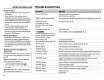
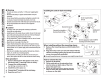
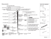
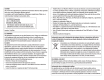
Table Of Contents
- Instruction Manual
- Installation / Connection
- Warranty

z
0
-
1-
u
w
z
z
0
u
..........
z
0
-
I-
cc
...1
...1
C(
1-
"'
z
-
16
A
Warning
•
The
unit
can
only
be used
with
a
12
V
DC
power
supply,
negative
ground.
•
Disconnect
the
battery's
negative
terminal
before
wiring
and
mounting.
•
Do
not
conned
Battery
wire
(yellow)
and
Ignition
wire
(red)
to
the
car
chassis
or
Ground
wire
(black)
to
prevent
a
short
circuit.
•
Insulate
unconnected
wires
with
vinyl
tape
to
prevent
a
short
circuit.
•
Be
sure
to
ground
this
unit
to
the
car's
chassis
again
after
installation
.
A
Caution
•
For
safety's
sake,
leave
wiring
and
mounting
to
professionals.
Consult
the
car
audio
dealer.
•
Install
this
unit
in
the
console
of
your
vehicle.
Do
not
touch
the
metal
parts
of
this
unit
during
and
shortly
after
use
of
the
unit.
Metal
parts
such
as
the
heat
sink
and
enclosure
become
hot.
•
Do
not
connect
the
8
wires
of
speakers
to
the
car
chassis
or
Ground
wire
(black),
or
conned
them
in
parallel.
•
Mount
the
unit
at
an
angle
of
less
than
30°.
• If
your
vehicle
wiring
harness
does
not
have
the
ignition
terminal,
conned
Ignition
wire
(red)
to
the
terminal
on
the
vehicle's
fuse
box
which
provides
12
V
DC
power
supply
and
is
turned
on
and
off
by
the
ignition
key.
•
After
the
unit
is
installed,
check
whether
the
brake
lamps,
blinkers,
wipers,
etc.
on
the
car
are
working
properly.
• If
the
fuse
blows,
first
make
sure
the
wires
are
not
touching
car's
chassis,
then
replace
the
old
fuse
with
one
that
has
the
same
rating.
Basic procedure
1 Remove
the
key
from
the
ignition
switch, then
disconnect
the
8 terminal
of
the
car battery.
2 Connect
the
wires properly.
See
Wiring
connection.(+
17)
3 Install
the
unit
to
your car.
See
Installing
the
unit
(in-dash mounting).
4 Connect
the
8
terminal
of
the
car battery.
5
Reset
the
unit.(+
3)
Do
the
required
wiring.
(+
17)
Bend
the
appropriate
tabs
to
hold
the
mounting
sleeve
firmly
in
place.
I
When
installing
without
the
mounting
sleeve
j 1
Remove
the
mounting
sleeve and
trim
plate
from
I
the
unit.
2 Align
the
holes in
the
unit
(on
both
sides)
with
the
1
vehicle
mounting
bracket and secure
the
unit
with
I
screws (commercially
available).
(s~L,,
@@
@®
l
u
I
l,
__
____l
r----~
'---------,
8 mm
MAX.[·
-~
~
---
-
-
~
-
~
MSmm MSmm
I
1
A
Use
only
the
specified
screws.
Using
wrong
screws
might
damage
the
unit.
I
How
to
remove
the
unit
1 Detach
the
faceplate.
2 Fit
the
catch pin on
the
extraction keys
into
the
holes on
both
sides
of
the
trim
plate, then
pull
it
out.
3
Insert
the
extraction keys deeply
into
the
slots on each side, then
follow
the
arrows
~--
a
_
s
_
s_h_o_w
_
n_o
_
n
_
t
_
h
__
e
_
r
_
ig
_
h
_
t
_
·----
-----------
----
----------
--~
=======-
--J