EQplus AUDIO PROCESSOR OPERATING MANUAL
EQplus AUDIO PROCESSOR OPERATING MANUAL September 2004 W2IHY TECHNOLOGIES Julius D. Jones 19 Vanessa Lane Staatsburg, N.Y. (12580) (845) 889-4253 E-mail: Julius@W2IHY.COM Home Page: http:// www.w2ihy.
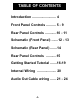
TABLE OF CONTENTS Introduction ......................... 4 Front Panel Controls .......... 5 - 9 Rear Panel Controls ............10 - 11 Schematic (Front Panel) .......12 - 13 Schematic (Rear Panel) .......14 Rear Panel Controls ...........15 Getting Started Tutorial .......16-19 Internal Wiring .................... 20 Audio Out Cable wiring ......
INTRODUCTION EQplus AUDIO PROCESSOR The EQplus is the next generation of audio processing equipment from W2IHY Technologies. The EQplus was designed to be directly attached to the world famous W2IHY 8 Band EQ. The EQplus provides features such as Audio Compression, Downward Expansion, Effects and connectivity to 3 radios. All these features, and more, were designed in a way that makes the EQplus easy to use.
FRONT PANEL CONTROLS 6 8 9 7 11 12 10 16 1 4 3 5 14 15 13 17 2 This section describes each of the controls on the front panel. You should read through this section now. Some of the descriptions will be more meaningful after you first work through the Getting Started Tutorial. (1) Power On/Off Switch (S1) This switch turns the unit's power on and off. (2) Power on LED (LED1) This LED goes on when power is on in the unit.
FRONT PANEL CONTROLS (4) Audio Input Impedance Switch (S5) This 3 position toggle switch is used to change the input impedance of the Mic and Aux Inputs (19,20 & 21). Input Impedances of 200 ohms, 600 ohms and 50K ohms ( HI-Z)may be selected. (5) Mic In Gain (R12) This potentiometer, when turned clockwise, can increase the Audio Input signal levels up to about +40dBv. The mic gain should be changed while speaking into the microphone, until 3 or 4 green Bar Graph (7) LED’s are illuminated.
FRONT PANEL CONTROLS (7) Equalizer On/Off Switch (S3) This switch turns the Equalizer on and off. When the equalizer is off, adjusting the bass and treble controls have no effect on the output audio. (8) Equalizer Bass (R37) This rotary potentiometer works only when the Equalizer Switch (7) is on. Turning this control clockwise increases the amount of bass boost. Turning this control counterclockwise decreases the amount of bass boost. The detent at the half way point of rotation represents 0 dB of boost.
FRONT PANEL CONTROLS Incoming signals will have up to 20dB of compression introduced. The EQplus compressor circuitry contains a limiter that is preset at the factory. The limiter is set to limit the processed signals to 375 millivolts (-9 dB). When this level is reached the 1-st yellow LED on the bar graph will be on and the top Red (Limiting) LED will turn on.
FRONT PANEL CONTROLS (14) EFFECTS PROCESSOR DELAY Potentiometer (R42) This potentiometer works only if the Effects Processor 3 position toggle switch is selecting either effect 1 or effect 2. The Delay control, when rotated clockwise increases, by up to about 80 milliseconds, the time that audio waveform is delayed. The delayed waveform is then mixed with the original non delayed waveform. The mixed waveform is next sent to the output of the EQplus.
REAR PANEL CONTROLS 21 22 19 18 20 22 25 23 24 (18) MIC SELECT This three position switch selects the YAESU, KENWOOD or ICOM microphone plugged into the 8 pin Mic Input (19). (Other microphones supported with mic adapters) (19) MIC INPUT This Input uses an 8 Pin microphone male connector. The impedance of this input is set by the Audio Input 3 position toggle switch (4). Do not use this connector when RCA Mic In (20) or the Aux Input (21) is being used.
REAR PANEL CONTROLS (20) MIC INPUT This RCA female connector is used as a microphone input. This connector works independent of the Mic Select switch (18) and may be used for another audio input source such as a microphone. The impedance of this input is set by the Audio Input 3 position toggle switch (4). (21) AUX INPUT This 5 Pin Din connector allows audio to be brought into the EQplus from an external device..
REAR PANEL CONTROLS (23) AUDIO OUTPUTS 1,2 and 3 The audio output and PTT outputs of the EQplus uses these 5 pin DIN’s. When the Audio Output Rotary switch (22) is in the “1” position, audio is active at Audio Output 1. When the Audio Output Rotary switch (22) is in the “2” position, audio is active at Audio Output 2. When the Audio Output Rotary Switch (22) is in the “3” position, audio is active at Audio Output 3. The diagram below shows the configuration of each of the 3 outputs.
GETTING STARTED TUTORIAL Before plugging the power transformer into the wall, preset the EQplus controls as indicated: Power , Equalizer, Compressor/ Downward and Effects Processor all off. Connect your microphone into the Mic In rear connector. Turn the Mic Select to select the microphone you will be using. If you are not using a mic but an external audio source like a W2IHY EQ, connect your audio source into the Aux Input.
GETTING STARTED TUTORIAL Audio Input Gain (5) so that 2 or 3 Green Bar Graph LED’s light up. This may require adjusting both the Mic Gain control on the 8 Band EQ and the Audio Gain control on the EQplus. Using The EQplus headphone (PHONES) Monitor Connect a set of stereo headsets into the 1/4 inch “Phones” Connector located in the back of the EQplus. Talk into the mic to hear audio coming from the EQplus.
GETTING STARTED TUTORIAL - Turn the Compressor control (11) fully counter clockwise. This setting passes uncompressed audio thru the compressor. Turning the compressor control clockwise increase the amount of compression. Set the compression to the desired level. You can turn the compression levels up to a point where talking into the mic causes the RED Limiting LED to come on .
GETTING STARTED TUTORIAL The Level control (15) sets the amplitude that the audio delayed by the Effects Processor combines with the non delayed audio. Through experimentation, the user can find what Effects Processor Delay and Level settings are best for their voice characteristics. Both the Delay and Level controls have detents half way through the rotation of the control. The detents may be used as a starting point for adjusting the Effects Processor. Controls.
INTERNAL WIRING PIN 7 PIN 1 -20- MIC IN
AUDIO OUT CABLE WIRING 5 PIN DIN AUDIO OUTPUT CONNECTION + Audio AUDIO OUT 1/2/3 5 Pin Male DIN Din connectors shown on side to be soldered Balanced Output - Audio Hi-Z Output PTT Gnd Low Impedance Balanced Output to Low Impedance Radio + Audio AUDIO OUT 1/2/3 5 Pin Male DIN - Audio Balanced Output PTT Din connectors shown on side to be soldered Gnd (Audio cable shield) Low Impedance Unbalanced Output to Low Impedance Radio + Audio AUDIO OUT 1/2/3 5 Pin Male DIN Din connectors shown on side to
AUDIO OUT CABLE WIRING + Mic Japan Radio JST-135 JST-245 Yaesu FT990/ft992 FT1000MP/M-V Alinco DX77 Kenwood TS130/140 TS430/440 TS850/TS870 TS930/940/950 SG2020 K2 8 Pin Mic Connector Pin 8 - Mic 8 Pin Mic Connector Pin 7 PTT Gnd 8 Pin Mic Connector Pin 6 Shield of Cable + Mic 8 Pin Mic Connector Pin 1 - Mic 8 Pin Mic Connector Pin 7 PTT Gnd 8 Pin Mic Connector Pin 2 Shield of Cable + Mic Yaesu FT102 FT747/757/767 FT847 FT1000/1000D PTT GND + Mic 8 Pin Mic Connector Pin 6 Shield of Cable ICOM
AUDIO OUT & POWER CABLE WIRING + Audio - Audio DRAKE T4XB COLLINS 32S 1, 32S3 COLLINS KWM2A HI-Z PTT Shield of Cable GND + Audio - Audio COLLINS 32V2, 32V3 Hallicrafters E.F.
AUDIO OUT CABLE WIRING + Audio - Audio LOW Z TRS BALANCED OUTPUT LOW-Z Shield of Cable GND + Audio - Audio HI Z TRS BALANCED OUTPUT HI-Z Shield of Cable GND + Audio - Audio LOW Z XLR BALANCED OUTPUT LOW-Z 3 Shield of Cable GND 1 2 - Audio HI-Z XLR BALANCED OUTPUT + HI-Z Audio Shield of Cable GND 1 2 HI-Z 3 + Audio - Audio LOW Z Single channel Input to Computer Sound Card LOW-Z Shield of Cable GND + Audio - Audio LOW Z UNBALNCED 1/4” MONO CONNECTOR LOW-Z GND Shield of Cable DIN