VR-507 KRF-V7050D Preparation AUDIO VIDEO SURROUND RECEIVER INSTRUCTION MANUAL KENWOOD CORPORATION This instruction manual is used to describe multiple models listed above. Model availability and features (functions) may differ depending on the country and sales area. B60-5027-00 01 MA (K, P, Y, M, X, I) *5027/01-09/EN 1 0009 3/15/01, 2:53 PM Additional Information Remote Control Compared to standard remote controls, the remote control supplied with this receiver has several operation modes.
Before applying the power Units are designed for operation as follows. 2 U.S.A. and Canada ........................................... AC 120 V only Australia ........................................................... AC 240 V only Europe and U.K. ............................................... AC 230 V only China and Russia ............................................ AC 220 V only Other countries ............
Before applying the power Contents Caution : Read the pages marked 3 carefully to ensure safe operation. Before applying the power ................... 2 Safety precautions .............................................. 2 Unpacking .......................................................... 2 How to use this manual ...................................... 4 Special features .................................................. 5 Additional Information In case of difficulty ...........................
Before applying the power 4 How to use this manual This manual covers the VR-507 and KRF-V7050D. Items such as functions, number of jacks, and remote control details somewhat differ between these models. To confirm the functions available on the model you have purchased, refer to the table below.
Before applying the power Special features 5 Multi channel music (SRS Circle Surround This receiver incorporates a wide variety of surround modes to bring you maximum enjoyment from your video software. Select a surround mode according to your equipment or the software you are going to play and enjoy! ∞ SRS Circle surround enables you to listen to multi channel sound from the stereo source.
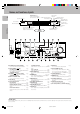
Names and functions of parts 6 Frequency display, Input display, Preset channel display, Surround mode display Speaker indicator SP A B TI.VOL CLIP MUTE RDS EON PTY TP TA NEWS CLIP indicator MUTE indicator L C LFE SL PRO LOGIC indicator DIGITAL indicator S.DIRECT indicator AUTO indicator MEMO indicator AUTO FM AUTO SOUND DIGITAL AUTO SOUND indicator Band indicators R AM PRO LOGIC S.DIRECT MEMO MHz 3 STEREO MONITOR ST.
Names and functions of parts Remote control unit (RC-R0720) (VR-507) This remote control unit can be used not only for Kenwood products but also for other non-Kenwood products by setting the appropriate maker setup codes. ⁄ POWER DVD CBL DSS CD VCR TV Preparation SET UP RECEIVER 1 2 3 4 5 6 7 8 9 MUTE 0 +10 + LSTN.M ENTER VOLUME ¢ + LAST SOUND DVD CHANNEL SLEEP CINE.EQ GUIDE SETUP INPUT 4 EXIT/RETURN MULTI CONTROL P.CALL P.CALL 4 ¢ SELECT REC M.
Names and functions of parts 8 Remote control unit (RC-R0613) (KRF-V7050D) This remote control unit can be used not only for Kenwood products but also for other non-Kenwood products by setting the appropriate maker setup codes. ⁄ POWER Preparations 1 1 2 # 3 TV 4 5 6 $ VCR 2 3 4 7 8 9 0 +10 RETURN LSTN M. MENU SET UP OSD SOUND 7 8 9 0 ! CABLE DSS POWER P.CALL P.CALL 5 6 DVD MULTI CONTROL TUNING B.BOOST RECEIVER TITLE PHONO A/B+100 DISC SKIP AUTO TV SEL. CD/DVD INPUT SEL.
Setting up the system DTS disclaimer clause DTS Digital Surround™ is a discrete 5.1 channel digital audio format available on CD, LD, and DVD software which consequently cannot be decoded and played back inside most CD, LD, or DVD players. For this reason, when DTS-encoded software is played back through the analog outputs of the CD, LD, or DVD player, excessive noise will be exhibited.
Setting up the system 10 Connecting audio components Shape of AC outlets U.S.A.
Setting up the system Connecting video components 11 About the S VIDEO jacks S Video jacks MONITOR OUT PLAY IN REC OUT PLAY IN PLAY IN PLAY IN DVD VIDEO 1 VIDEO 1 VIDEO 2 VIDEO 3 PLAY IN REC OUT PLAY IN PLAY IN S VIDEO Use the S VIDEO jacks to make connections to video components with S VIDEO IN/OUT jacks.
Setting up the system Connecting a DVD player (6-channel input) 12 If you have connected a DVD player to the receiver with digital connection, be sure to read the “Input mode settings” section carefully.
Setting up the system Digital connections PLAY IN REC OUT PLAY IN PLAY IN PLAY IN L MONITOR OUT DVD VIDEO 1 VIDEO 1 VIDEO 2 VIDEO 3 R R B L 75µs AM 10kHz FM 100kHz 50µs AM 9kHz FM 50kHz R A R L L C DEEMPHASIS CHANNEL SPACE OPTICAL DIGITAL OUT (AUDIO) DVD Optical fiber cable CD or DVD player VIDEO 2 COAXIAL CD/DVD OPTICAL VIDEO 3 OPTICAL DIGITAL IN Optical fiber cable OPTICAL DIGITAL OUT (AUDIO) Component with DTS, Dolby Digital, or PCM OPTICAL DIGITAL OUT Connect the video sign
Setting up the system 14 Connecting to the AV AUX jacks The AV AUX jacks are convenient for connection of video components such as a camcorder or a video game. Connecting the antennas AM loop antenna The supplied loop antenna is for use indoors. Place it as far as possible from the receiver, TV set, speaker cords and power cord, and adjust the direction for best reception. AM antenna terminal connections 1 Push lever. 2 Insert cord. 3 Release lever.
Setting up the system Connecting the system control 15 This unit is compatible only with the [SL-16] mode. The system control operation is not available if the unit is connected in the [XS8], [XS], or [XR] connection mode. If your component has the mode select switch, set the connected components to the [SL16] mode. SYSTEM CONTROL OPERATIONS Remote Control Lets you operate this unit with the system remote supplied with the receiver.
Setting up the system 16 Connecting the speakers Front Speakers A Left Right Preparations Center Speaker FRONT SPEAKERS RED CENTER SPEAKER BLUE GREEN + PLAY IN REC OUT PLAY IN PLAY IN PLAY IN L MONITOR OUT DVD VIDEO 1 VIDEO 1 VIDEO 2 VIDEO 3 R R B L 75µs AM 10kHz FM 100kHz 50µs AM 9kHz FM 50kHz R A R L L C DEEMPHASIS CHANNEL SPACE SUB WOOFER PRE OUT FRONT SPEAKERS + + ORANGE GRAY SURROUND SPEAKERS Powered subwoofer Right Left Surround Speakers (Be sure to connect both
Setting up the system Connecting the terminals 2 Loosen. 1 Secure. 3 Insert. 4 Secure. 2 Insert. • Sound will not be heard if the speaker terminal is not fully secured. • Never short circuit the + and – speaker cords. • If the left and right speakers are connected inversely or the speaker cords are connected with reversed polarity, the sound will be unnatural with ambiguous acoustic imaging. Be sure to connect the speakers correctly. 1 Strip coating. 2 Push the lever.
Setting up the system Preparing the remote control 18 For VR-507 (RC-R0720) Speaker placement Loading the batteries 1 Remove the cover. 2 Insert the batteries. Center speaker Preparations 3 Close the cover. 1 Subwoofer Front speaker 2 Listening position Surround speaker • Insert two AA-size (R6) batteries as indicated by the polarity markings. Front speakers : Place to the front left and right of the listening position. Front speakers are required for all surround modes.
Preparing for surround sound To enable you to obtain optimum enjoyment from the receiver’s listening modes, make sure to complete the speaker settings (subwoofer, front, center, and surround speakers) as described below. If you selected “LRG” as the front speakers setting, 1 CNTR LRG (large): A large center speaker is connected to the receiver. 2 CNTR NML (normal): An average size center speaker is connected to the receiver. 3 CNTR OFF: Center speaker setting mode to the receiver is OFF.
Preparing for surround sound Normal playback Preparing for playback 20 4 Input the distance to the speakers. Some preparatory steps are needed before starting playback. 1 Measure the distance from the listening position to each of the speakers. ON/STANDBY INPUT MODE AUTO/CINEMA EQ. POWER INPUT SELECTOR Jot down the distance to each of the speakers.
Normal playback Adjusting the sound Listening to a source component 21 MULTI CONTROL SOURCE DIRECT SOUND VOLUME CONTROL INPUT SELECTOR SPEAKERS A/B PHONES VOLUME CONTROL VOLUME MUTE VOLUME MULTI CONTROL INPUT SELECTOR SOUND SOUND MULTI CONTROL B. BOOST VOLUME MUTE RC-R0613 RC-R0720 1 Use the INPUT SELECTOR knob to select the source you want to listen to. The input sources change as shown below: Selecting a source using the INPUT SELECTOR knob.
Normal playback 22 Recording Recording audio (analog sources) Muting the sound MONITOR The MUTE key lets you mute the sound of the speakers. Press the MUTE key. SP A B TI.VOL MUTE CLIP RDS EON PTY TP TA NEWS To cancel L C LFE LS R SW S RS Blinks INPUT SELECTOR Press the MUTE key again so that the “MUTE” indicator goes off. • MUTE ON can also be deactivated by turning the volume control knob.
Recording Listening to radio broadcasts The receiver can store up to 40 stations in the memory and recall them by one-touch operation. Recording video 1 Use the INPUT SELECTOR to select the video source (other than “VIDEO1”) you want to record. 23 Tuning radio stations 2 Set the video deck connected to VIDEO 1 to record. • Select the REC MODE to record a digital input source. MULTI CONTROL 3 Start playback, then start recording. • Recording may not be normal for some video software.
Listening to radio broadcasts 24 Presetting radio stations manually Receiving preset stations in order (P.CALL) MULTI CONTROL MEMORY P.CALL 4/¢ TUNER 1 Tune to the station you want to store. RC-R0613 2 Press the MEMORY key while receiving the station. Blinks for 5 seconds SP A B TI.VOL CLIP MUTE RDS EON PTY TP TA NEWS L C LFE LS Lights for 5 seconds FM AUTO SOUND DIGITAL AUTO AM PRO LOGIC S.DIRECT MEMO MHz 3 STEREO MONITOR ST.
Ambience effects This receiver is equipped with listening modes that allow you to enjoy an enhanced sonic ambience with a variety of video sources. In order to obtain the optimum effect from the surround modes, make sure to input the proper speaker settings beforehand. ( Surround modes DTS The DTS multi-channel audio format is available on CD, LD and DVD software. DTS is a strictly digital format and can not be decoded inside most CD, LD or DVD players.
Ambience effects 26 Dolby PRO LOGIC II DSP mode Dolby Pro Logic II was designed specifically to provide a new sense of spatiality, directionality and articulation of sounds from Dolby Surround encoded sources (such as video and Laserdisc software marked ). This is achieved with an intelligent, built-in feedback logic design, a matrix surround decoding and the decoding of stereo, full bandwidth surround outputs. The PRO LOGIC II modes programmed into this receiver are “MOVIE”, “MUSIC” and “PRO LOGIC”.
Ambience effects Surround play 27 When the DOLBY DIGITAL signal is input: The DTS compatible models can reproduce a CD, DVD, or LD carrying the DTS mark. DOLBY DIGITAL can be used when playing DVD or LD software bearing mark and DOLBY DIGITAL format digital broadcasts (etc.). the DOLBY PRO LOGIC and DOLBY 3 STEREO can be used when playing mark. video, DVD, or LD software bearing the INPUT MODE INPUT SELECTOR (The DOLBY DIGITAL, PROLOGIC, or 3 STEREO indicator lights up.
Ambience effects 28 DVD 6-channel playback Convenient functions Using a DVD player or the like equipped with six (5.1) output channels and the receiver, you can enjoy surround sound playback. When you try to play a disc other than Dolby Digital such as DTS CD, no sound is produced or, noise may be heard. To avoid this situation, make sure that you connect the component to the receiver’s DVD/6ch. INPUT jacks through a surround processor which can decode the surround signal you want to listen to.
Ambience effects Dimension mode (Pro Logic II music mode only) Midnight mode (Dolby Digital mode only) When watching movies at night , you might not be able to raise the volume as loud as normal. Midnight mode compresses the dynamic range of previously specified parts of the Dolby Digital sound track (like scenes with sudden increases in volume) to minimize the difference in volume between the specified and non-specified parts.
Ambience effects 30 Subwoofer adjustment It is easy to adjust the volume of the subwoofer using the remote control. 1 Press the SOUND key repeatedly until “SW” appears on the display. SP A B TI.VOL CLIP MUTE RDS EON PTY TP TA NEWS L C LFE SL AUTO FM AUTO SOUND DIGITAL AM PRO LOGIC S.DIRECT MEMO MHz 3 STEREO MONITOR ST. TUNED kHz DOWN MIX DSP R SW S SR 2 Use MULTI CONTROL knob or keys to adjust the volume. •The adjustment range is –10 dB to +10 dB.
Basic remote control operations for other components (For VR-507) The remote control supplied with this receiver) is also capable of controlling components from a variety of manufacturers once you register the appropriate setup codes into the remote control unit. 5 Repeat steps 2 to 4 to register additional components Low battery warning Notes • Although each setup code is designed to work with a number of different models, certain codes may not work with some models.
Basic remote control operations for other components 32 Searching for your code Re-assigning device keys If your component does not respond after trying all the codes listed for your component, or if your component is not listed at all, try searching for your code. For example, to search for a code for your TV: The remote control can be set up to control a second TV or VCR, or any combination of eight home entertainment components.
Basic remote control operations for other components Changing volume lock Operating other components The remote control is set to control volume of a component through your TV while in the TV, VCR, or Cable mode. However, in an Audio mode (i.e. CD), you have separate control of your audio component’s volume. If your TV is not remote controllable, or if you want volume to be controlled by a different component, you can change the Volume Lock setting to control a volume through a non-associated mode (e.g.
Basic remote control operations for other components (For KRF-V7050D) 34 The remote control supplied with this receiver is also capable of controlling components from a variety of manufacturers once you register the appropriate setup codes into the remote control unit. Low battery warning Replace all two batteries with new ones when you notice a shortening of the distance from which the remote control will operate. The remote control is designed to retain setup codes in memory while you change batteries.
Basic remote control operations for other components Setup code chart (for VR-507 (RC-R0720)) 35 TV Setup codes Maker Setup codes Maker Setup codes Maker AOC Admiral Aiko Akai Alaron Ambassador America Action Ampro Anam Audiovox Baysonic Belcor Bell & Howell Bradford Brockwood Broksonic CXC Candle Carnivale Carver Celebrity Cineral Citizen 0030, 0019 0093, 0463 0092 0030 0179 0177 0180 0751 0180 0451,0180, 0092, 0623 0180 0019 0154, 0016 0180 0019 0236, 0463 0180 0030, 0056 0030 0054 0000 0451, 009
Basic remote control operations for other components 36 Setup code chart (for VR-507 (RC-R0720)) VCR Setup codes Maker Setup codes Admiral Adventura Aiko Aiwa Akai America Action American High Asha Audiovox Beaumark Bell & Howell Broksonic CCE Calix Canon Carver Cineral Citizen Colt Craig Remote Control 0048,0209 0000 0278 0037, 0000 0041 0278 0035 0240 0037 0240 0104 0184, 0121, 0209, 0002 0072, 0278 0037 0035 0081 0278 0037, 0278 0072 0037, 0047, 0240, 0072, 0271 CurtisMathes 0060, 0035, 0041, 0162
Basic remote control operations for other components Cable tuner Setup codes Maker DBS/DSS receiver Setup codes Setup codes Maker ABC 0003, 0008, 0014, 0017, 0007, 0011, 0013 Allegro 0153, 0315 Archer 0153, 0797 Bell & Howell 0014 Century 0153 Citizen 0153, 0315 Comtronics 0040 Contec 0019 Eastern 0002 Emerson 0797 Everquest 0015,0040 Focus 0400 Garrard 0153 Gemini 0015 General Instrument 0476, 0276, 0011, 0810 GoldStar 0144, 0040 Goodmind 0797 Hamlin 0020, 0259, 0009, 0034 Hitachi 0011 Hytex 0007 Jas
Basic remote control operations for other components 38 Setup code chart (for VR-507 (RC-R0720)) DVD player Setup codes CD player Setup codes DBS/DSS audio service Setup codes Maker Setup codes Maker Setup codes Maker Setup codes Aiwa Burmester California Audio Lab Carver DKK Denon Emerson Fisher Garrard Genexxa Harman/Kardon Hitachi JVC Kenwood 0157, 0124 0420 0029, 0303 0157, 0179, 0437 0000 0003, 0873 0305 0179, 0174 0420, 0393 0032, 0305 0157, 0173 0032 0072 0028, 0037, 0190, 0626, 0681, 082
Basic remote control operations for other components Setup code chart (for KRF-V7050D (RC-R0613)) VCR Setup codes TV Setup codes ZENITH MAGNAVOX SHARP PANASONIC SAMSUNG JVC HITACHI PIONEER PROSCAN QUASAR PHILIPS SANYO TOSHIBA MITUBISHI LOEWE Setup codes 101 102 103, 104, 105, 106, 117 107, 108 109 110 111,112, 122 109 113 114, 115 116 117 118 109 119 120 121 123, 124 CABLE Setup codes Maker JERROLD S.ATLANTA ZENITH PIONEER TOCOM G.I.
Basic remote control operations for other components 40 CASSETTE deck, CD player & MD recorder operations You can perform these basic operations using the keys described below when connected to KENWOOD cassette deck, MD recorder or CD player equipped with system control operations. % Cassette deck operations keys POWER SET UP POWER DVD CBL VCR TV RECEIVER DSS CD 1 2 3 4 5 6 7 8 9 0 +10 RETURN LSTN M. TV 1 2 3 4 5 6 7 8 9 MUTE 0 VCR +10 DVD ENTER + VOLUME LISN.
Basic remote control operations for other components CD player operation keys 41 POWER SET UP POWER DVD CBL VCR TV Numeric keys (Select tracks) RECEIVER DSS CD 1 2 3 4 5 6 7 8 9 0 +10 RETURN LSTN M. TV 1 2 3 4 5 6 7 8 9 MUTE 0 Numeric keys (Select tracks) VCR +10 DVD CABLE ENTER MENU SET UP ¢ LSTN.M + + LAST CINE.EQ INPUT SETUP DSS P.CALL SLEEP GUIDE OSD SOUND POWER SOUND DVD CHANNEL VOLUME P.
Basic remote control operations for other components 42 Other components’ operations Refer to the following for the type of remote control operations available for each component. 1 Select the input source. 2 Press the keys corresponding to the operations you desire. Refer to the following sections for details. • When pressing keys in succession, press each key firmly and be sure to wait at least 1 second before pressing the next key.
Basic remote control operations for other components VCR operation keys 43 POWER SET UP DVD CBL DSS CD VCR TV POWER RECEIVER Numeric Keys Numeric keys 1 2 3 4 5 6 1 2 3 4 5 6 7 8 9 0 +10 RETURN LSTN M. MENU SET UP OSD SOUND TV VCR 7 8 9 MUTE 0 +10 + LISN.M ENTER ¢ + LAST CHANNEL +/– (Channel +/–) SOUND DVD CHANNEL VOLUME SLEEP CINE.EQ ¢ 1 (Rewind) ¡ (Fast forward) SELECT ¶ REC P.CALL MULTI CONTROL P.CALL 4 1 (Rewind) P.
Basic remote control operations for other components 44 DBS/DSS receiver operation keys POWER SET UP DVD CBL DSS CD VCR TV RECEIVER POWER 1 2 3 4 5 6 7 8 9 MUTE 0 Numeric keys Numeric keys 1 2 3 4 5 6 7 8 9 0 +10 RETURN LSTN M. TV VCR +10 ENTER LISN.M + ¢ + LAST SOUND DVD CHANNEL VOLUME SLEEP CINE.EQ INPUT GUIDE SETUP CHANNEL +/– (Channel +/–) 4 MENU (Menu) OSD (OSD menu) MENU SET UP OSD SOUND DSS POWER P.CALL EXIT/RETURN DVD CABLE P.
In case of difficulty Resetting the Microcomputer The microcomputer may malfunction (unit cannot be operated, or shows an erroneous display) if the power cord is unplugged while the power is ON, or due to some other external factor. If this happens, execute the following procedure to reset the microcomputer and return the unit to its normal operating condition. 45 For U.S.A. and Canada Unplug the power cord from the wall outlet, then plug it back in while holding down the POWER key.
In case of difficulty Remote control unit 46 Symptom Cause Remedy Certain inputs cannot be selected using the remote control. • No setup codes registered at for the respective input(s). • Register a setup code at the respective input(s). fi· Remote control operation is not possible. • The remote control is set to a different operation mode. • Batteries are exhausted.
Specifications Caution : Read this page carefully to ensure safe operation. For U.S.A and Canada AUDIO section (VR-507) DIGITAL AUDIO section Rated power output during STEREO operation Sampling frequency ...................... 32 kHz, 44.1 kHz, 48 kHz, 96kHz Input level / impedance / wave length Optical ........................... (–15 dBm ~ –21 dBm), 660 nm ±30nm Coaxial ................................................................. 0.
For your records Record the serial number, found on the back of the unit, in the spaces designated on the warranty card, and in the space provided below. Refer to the model and serial numbers whenever you call upon your dealer for information or service on this product.