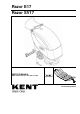
Razor E17 Razor SV17 SERVICE MANUAL KENT model: 908 7113 020 - 908 7112 020 909 6577 000(1)2006-02
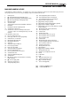
SERVICE MANUAL TABLE OF CONTENTS GENERAL INFORMATION .................................................................................................................. 2 GENERAL INFORMATION .............................................................................................................. 2 MACHINE LIFTING ..................................................................................................................... 2 MACHINE TRANSPORTATION .................................................
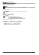
SERVICE MANUAL GENERAL INFORMATION GENERAL INFORMATION GENERAL INFORMATION NOTE Forward and backward, front and rear, left and right are intended with reference to the operator's position. MACHINE LIFTING WARNING! Do not work under the lifted machine without supporting it with safety stands.
SERVICE MANUAL GENERAL INFORMATION SAFETY Kent uses the following symbols to indicate potentially dangerous situations. Always read this information carefully and take all necessary precautions to safeguard people and property. DANGER! It indicates a dangerous situation with risk of death for the operator. WARNING! It indicates a potential risk of injury for people. CAUTION! It indicates a caution or a remark related to important or useful functions.
SERVICE MANUAL GENERAL INFORMATION WARNING! [RAZOR SV 17 - RAZOR E 17] – Carefully read all the instructions before carrying out any maintenance/repair procedure. – To reduce the risk of fire, electric shock, or injury, do not leave the machine unattended when it is plugged in. Unplug the machine from the outlet when not in use and before servicing. – To avoid electric shock, do not expose to rain. Store the machine indoors. – Do not allow to be used as a toy.
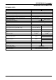
SERVICE MANUAL GENERAL INFORMATION TECHNICAL DATA General RAZOR SV 17 RAZOR E17 Cleaning width 17.0 in (430 mm) Machine width (without squeegee) 22.4 in (570 mm) Minimum machine length with adjustable handlebar 36.6 in (930 mm) Minimum machine height with adjustable handlebar 40.2/44.7 in (1,020/1,135 mm) Squeegee width 720 mm (28.3 in) Machine weight (with batteries, battery charger and brush) Machine weight (with brush) 233.7 lb (106 Kg) - - 148.8 lb (67.
SERVICE MANUAL GENERAL INFORMATION MAINTENANCE SCHEDULED MAINTENANCE The lifespan of the machine and its maximum operating safety are ensured by correct and regular maintenance. See the GENERAL INFORMATION and SAFETY paragraphs. Provided below is the Scheduled Maintenance Table. The intervals shown may vary according to particular working conditions, which are to be defined by the person in charge of the maintenance. For instructions on maintenance procedures, see the following paragraphs.
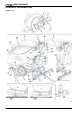
SERVICE MANUAL GENERAL INFORMATION MACHINE NOMENCLATURE In this Manual, numbers in brackets – for example: (2) - refer to the components shown in the nomenclature pages. Refer to these pages whenever it is necessary to identify a component mentioned in the text. 1. 2. 3. 4. 5. 6. 7. 8. 9. 10. 11a.
SERVICE MANUAL GENERAL INFORMATION [RAZOR SV 17] S301386 8 909 6577 000(1)2006-02
SERVICE MANUAL GENERAL INFORMATION [RAZOR SV 17] S301387 909 6577 000(1)2006-02 9
SERVICE MANUAL GENERAL INFORMATION [RAZOR E 17] S301388 10 909 6577 000(1)2006-02
SERVICE MANUAL GENERAL INFORMATION [RAZOR E 17] S301389 909 6577 000(1)2006-02 11
SERVICE MANUAL SOLUTION SYSTEM SOLUTION TANK CLEANING [RAZOR SV 17 - RAZOR E 17] SOLUTION SYSTEM 1. 2. 3. 4. Drive the machine to the appointed disposal area. Check that the switches (5 and 6) are turned to “0”. If necessary, empty the tank (44) by means of the valve (24). Wash the tank (44) with clean water, then drain the water from the tank by means of the valve (24). SOLUTION FILTER CLEANING [RAZOR SV 17 - RAZOR E 17] 1. 2. 3. Check that the switches (5 and 6) are turned to “0”.
SERVICE MANUAL SOLUTION SYSTEM SOLUTION FLOW CONTROL TAP OR SOLENOID VALVE DISASSEMBLY/ASSEMBLY [RAZOR SV 17 - RAZOR E 17] Preliminary procedures 1. 2. Remove the batteries. Use a protection to avoid damaging the machine and tilt it carefully to lay its right side on the floor. Solenoid valve disassembly 3. 4. 5. Remove the screw (B) and disconnect the solenoid valve connector (C). Remove the screws (D) and move the solenoid valve (E). Disconnect the hoses (F) and (G) and recover the solenoid valve (E).
SERVICE MANUAL SOLUTION SYSTEM TROUBLESHOOTING [RAZOR SV 17 - RAZOR E 17] SMALL AMOUNT OF THE SOLUTION OR NO SOLUTION REACHES THE BRUSH Possible causes: 1. 2. 3. 4. 5. The solution filter is clogged/dirty (clean). The solution flow adjusting tap is clogged/dirty (replace). The solenoid valve is broken or there is an open in the electrical connection (replace the solenoid valve/repair the electrical connection). There is debris in the solution tank clogging the output hole (clean the tank).
SERVICE MANUAL BRUSHING SYSTEM BRUSH MOTOR ELECTRICAL INPUT CHECK [RAZOR SV 17] BRUSHING SYSTEM WARNING! This procedure must be performed by qualified personnel only. 1. 2. 3. 4. 5. 6. 7. Check that the brush (A) is installed on the machine. Drive the machine on a level ground. Check that the switches (5 and 6) are turned to “0”. If there is recovery water in the tank (43), drain it through the hose (22). Disconnect the vacuum hose (29) from the squeegee (17). Open the cover (12).
SERVICE MANUAL BRUSHING SYSTEM S301370 16 909 6577 000(1)2006-02
SERVICE MANUAL BRUSHING SYSTEM BRUSH MOTOR ELECTRICAL INPUT CHECK [RAZOR E 17] WARNING! This procedure must be performed by qualified personnel only. 1. 2. 3. 4. 5. 6. 7. Check that the brush (A) is installed on the machine. Drive the machine on a level ground. Check that the switches (5 and 6) are turned to “0”. If there is recovery water in the tank (43), drain it through the hose (22). Disconnect the vacuum hose (29) from the squeegee (17). Open the cover (12).
SERVICE MANUAL BRUSHING SYSTEM S301371 18 909 6577 000(1)2006-02
SERVICE MANUAL BRUSHING SYSTEM BRUSH MOTOR CARBON BRUSH CHECK AND REPLACEMENT [RAZOR SV 17] 1. 2. 3. 4. 5. 6. Remove the brush/pad-holder deck (see the procedure in the relevant paragraph). At the workbench, remove dust and dirt from the outside of the motor, then disengage and remove the clamp (A). Lift the retaining spring (B) of each carbon brush, then remove the four carbon brushes (C). Check if the four carbon brushes are worn out.
SERVICE MANUAL BRUSHING SYSTEM BRUSH MOTOR AND REDUCTION UNIT DISASSEMBLY/ASSEMBLY [RAZOR SV 17] Motor/reduction unit disassembly/assembly 1. 2. 3. 4. 5. 6. 7. 8. Remove the brush/pad-holder (54/55), according to the instructions in the Instructions for Use Manual. Remove the brush/pad-holder deck. At the workbench, remove the central screw (A). Remove the polygonal support (B). Recover the key (C). Remove the screws (D). Remove the brush motor (E). Reassemble in the reverse order of disassembly.
SERVICE MANUAL BRUSHING SYSTEM BRUSH MOTOR AND REDUCTION UNIT DISASSEMBLY/ASSEMBLY [RAZOR E 17] Motor/reduction unit disassembly/assembly 1. 2. 3. 4. 5. 6. 7. 8. Remove the brush/pad-holder (54/55), according to the instructions in the Instructions for Use Manual. Remove the brush/pad-holder deck. At the workbench, remove the central screw (A). Remove the polygonal support (B). Recover the key (C). Remove the screws (D). Remove the brush motor (E). Reassemble in the reverse order of disassembly.
SERVICE MANUAL BRUSHING SYSTEM TROUBLESHOOTING [RAZOR SV 17] OPEN CIRCUIT The brush motor fuse F1 determines the open circuit. This system allows to prevent the brush motor and circuits from being damaged under overload conditions. If there is an open in the circuit, the possible causes are: 1. Bulky debris or cords around the brush or between the brush and its flange (remove the brush and the debris or cords). 2. The brush motor electrical input is too high (check the electrical input).
SERVICE MANUAL RECOVERY WATER SYSTEM TANK AND VACUUM GRID WITH FLOAT CLEANING [RAZOR SV 17 - RAZOR E 17] RECOVERY WATER SYSTEM 1. 2. 3. 4. 5. 6. Drive the machine to the appointed disposal area. Check that the switches (5 and 6) are turned to “0”. If necessary, empty the tank (43) by means of the hose (22). Lift the cover (41), then wash with clean water the cover, the tank (43) and the vacuum grid (46). Drain the water in the tank through the hose (22).
SERVICE MANUAL RECOVERY WATER SYSTEM VACUUM SYSTEM MOTOR ELECTRICAL INPUT CHECK [RAZOR SV 17 - RAZOR E 17] WARNING! This procedure must be performed by qualified personnel only. 1. 2. 3. 4. 5. 6. 7. Drive the machine on a level ground. Check that the switches (5 and 6) are turned to “0”. If there is recovery water in the tank (43), drain it through the hose (22). Disconnect the vacuum hose (29) from the squeegee (17). Open the cover (12).
SERVICE MANUAL RECOVERY WATER SYSTEM S301373 [The figure shows RAZOR SV 17] 909 6577 000(1)2006-02 25
SERVICE MANUAL RECOVERY WATER SYSTEM VACUUM SYSTEM MOTOR CARBON BRUSH CHECK AND REPLACEMENT [RAZOR SV 17 - RAZOR E 17] 1. 2. 3. 4. 5. 6. 7. Remove the vacuum system motor (see the procedure in the relevant paragraph). At the workbench, disengage the fasteners (A) and (B), then remove the cover (C) from the vacuum system motor. Remove the screws (D) and the fasteners (E). Disconnect the electrical connections (F) and remove the brushes (G). Check the carbon brushes for wear.
SERVICE MANUAL RECOVERY WATER SYSTEM VACUUM SYSTEM MOTOR DISASSEMBLY/ASSEMBLY [RAZOR SV 17 - RAZOR E 17] 1. 2. 3. 4. 5. 6. 7. 8. 9. 10. Check that the switches (5 and 6) are turned to “0”. If there is recovery water in the tank (43), drain it through the hose (22). Disconnect the vacuum hose (29) from the squeegee (17). Open the cover (12).
SERVICE MANUAL RECOVERY WATER SYSTEM SQUEEGEE DISASSEMBLY/ASSEMBLY [RAZOR SV 17 - RAZOR E 17] 1. 2. 3. 4. 5. Check that the switches (5 and 6) are turned to “0”. Lower the squeegee (17) by means of the lever (25). Disconnect the vacuum hose (29) from the squeegee. Loosen the handwheels (18) and remove the squeegee (17). Reassemble in the reverse order of disassembly.
SERVICE MANUAL RECOVERY WATER SYSTEM TROUBLESHOOTING [RAZOR SV 17] OPEN CIRCUIT The vacuum system motor fuse 1 determines the open circuit. This system allows to prevent the vacuum system motor and its circuits from being damaged under overload conditions. If there is an open in the circuit, the possible causes are: 1. The motor is damaged (check the motor carbon brushes/electrical input). 2. The electrical input is excessive (check the motor for proper rotation).
SERVICE MANUAL OTHER SYSTEMS MACHINE SPEED ADJUSTMENT [RAZOR SV 17 - RAZOR E 17] OTHER SYSTEMS 1. 2. 3. 4. 5. 6. 7. 8. Check that the switches (5 and 6) are turned to “0”. If there is recovery water in the tank (43), drain it through the hose (22). Disconnect the vacuum hose (29) from the squeegee (17). Open the cover (12).
SERVICE MANUAL OTHER SYSTEMS BRUSH/PAD-HOLDER DECK DISASSEMBLY/ASSEMBLY [RAZOR SV 17] Disassembly 1. 2. 3. 4. 5. 6. 7. Remove the batteries. Remove the caps (A) and disconnect the electrical connections from the brush motor (B). Remove the left deck fastening screw (58). Use a protection (D) to avoid damaging the machine and tilt it carefully to lay its left side on the floor. Disconnect the solution hose (E) from the solenoid valve (F). Remove the right deck fastening screw (57). Remove the deck (H).
SERVICE MANUAL OTHER SYSTEMS BRUSH/PAD-HOLDER DECK DISASSEMBLY/ASSEMBLY [RAZOR E 17] Disassembly 1. 2. 3. 4. 5. 6. 7. 8. 9. 10. 11. 12. Check that the switches (5 and 6) are turned to “0”. If there is recovery water in the tank (43), drain it through the hose (22). Disconnect the vacuum hose (29) from the squeegee (17). Open the cover (12).
SERVICE MANUAL OTHER SYSTEMS S301377 S301222 909 6577 000(1)2006-02 33
SERVICE MANUAL ELECTRICAL SYSTEM (WET OR GEL) BATTERY REMOVAL/INSTALLATION AND SETTING [RAZOR SV 17] ELECTRICAL SYSTEM Disassembly 1. 2. 3. 4. 5. 6. 7. Check that the switches (5 and 6) are turned to “0”. If there is recovery water in the tank (43), drain it through the hose (22). Disconnect the vacuum hose (29) from the squeegee (17). Open the cover (12).
SERVICE MANUAL ELECTRICAL SYSTEM S301378 909 6577 000(1)2006-02 35
SERVICE MANUAL ELECTRICAL SYSTEM BATTERY CHARGING [RAZOR SV 17] NOTE Charge the batteries when the warning light (3) or (4) turns on, or when finishing cleaning. Keeping the batteries charged makes them last longer. CAUTION! When the batteries are discharged, charge them as soon as possible, as that condition makes them last shorter. Check for battery charge at least once a week. WARNING! When using lead (WET) batteries, battery charging produces highly explosive hydrogen gas.
SERVICE MANUAL ELECTRICAL SYSTEM Battery charging with (optional) battery charger installed on the machine 11. Connect the battery charger cable (27) to the electrical mains (the mains voltage and frequency must be compatible with the battery charger values: see the battery charger Manual). NOTE When the battery charger is connected to the electrical mains, all machine functions are automatically cut off. The green warning light (34) flashes when the battery charger is charging the batteries. 12. 13.
SERVICE MANUAL ELECTRICAL SYSTEM ELECTRONIC BOARD REPLACEMENT [RAZOR SV 17] 1. 2. 3. 4. 5. 6. 7. Check that the switches (5 and 6) are turned to “0”. Only for machine supplied without on-board battery charger: Disconnect the battery connector (36). Only for machine supplied with on-board battery charger: Remove the recovery water tank and disconnect the battery negative terminal (50) according to the following procedure: – If there is recovery water in the tank (43), drain it through the hose (22).
SERVICE MANUAL ELECTRICAL SYSTEM S301379 909 6577 000(1)2006-02 39
SERVICE MANUAL ELECTRICAL SYSTEM FUSE CHECK/REPLACEMENT [RAZOR SV 17] 1. 2. 3. 4. 5. 6. Check that the switches (5 and 6) are turned to “0”. Only for machine supplied without on-board battery charger: Disconnect the battery connector (36). Only for machine supplied with on-board battery charger: Remove the recovery water tank and disconnect the battery negative terminal (50) according to the following procedure: – If there is recovery water in the tank (43), drain it through the hose (22).
SERVICE MANUAL ELECTRICAL SYSTEM S301380 909 6577 000(1)2006-02 41
SERVICE MANUAL ELECTRICAL SYSTEM COMPONENT LOCATION [RAZOR SV 17] CH1: C1: EB1: EB2: ES1: ES2: EV1: F1: F2: F3: IS1: M1: M2: SW1: SW2: Battery charger Battery charger connector Electronic board (CF BA430) Electronic board led (CF BALED) Brush switch Vacuum switch Water solenoid valve Brush fuse (40A) Vacuum system fuse (30A) Solenoid valve and electronic board fuse (5A) Negative insulator Brush/pad motor Vacuum system motor Brush/pad switch Vacuum switch S301391 42 909 6577 000(1)2006-02
SERVICE MANUAL ELECTRICAL SYSTEM S301392 909 6577 000(1)2006-02 43
SERVICE MANUAL ELECTRICAL SYSTEM COMPONENT LOCATION [RAZOR E 17] EV1: FR: M1: M2: PL: SW1: SW2: Solenoid valve Frame Brush/pad motor Vacuum system motor Plug Brush/pad switch Vacuum switch S301393 44 909 6577 000(1)2006-02
SERVICE MANUAL ELECTRICAL SYSTEM WIRING DIAGRAM [RAZOR SV 17] Key: CH1: C1: EB1: EB2: ES1: ES2: EV1: F1: F2: F3: IS1: M1: M2: SW1: SW2: Battery charger Battery charger connector Electronic board (CF BA430) Electronic board LED (CF BALED) Brush switch Vacuum switch Water solenoid valve Brush fuse (40A) Vacuum system fuse (30A) Solenoid valve and electronic board fuse (5A) Negative insulator Brush/pad motor Vacuum system motor Brush/pad switch Vacuum switch Color code BK Black BU Blue BN Brown GN Green GY
SERVICE MANUAL ELECTRICAL SYSTEM WIRING DIAGRAM [RAZOR E 17] Key: EV1: FR: M1: M2: PL: SW1: SW2: Solenoid valve Frame Brush/pad motor Vacuum system motor Plug Brush/pad switch Vacuum switch Color BK BU BN GN GY OG PK RD VT WH YE code Black Blue Brown Green Grey Orange Pink Red Violet White Yellow S301395 46 909 6577 000(1)2006-02
14600 21st Avenue North Plymouth, MN, 55447-3408 www.kenteuroclean.