
Manual


Page 2
GENERAL DESCRIPTION
The SmartSonic Acoustic Wave Transmitter is designed for high accuracy level measurement of a variety of liquids. The
SmartSonic Integral can also be used for Open Channel Flow Measurement.
PRINCIPLE OF OPERATION
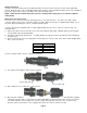
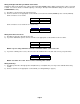
MODEL DESCRIPTION
P50-L35V-6N8AE - Remote Transmitter KAWT-xx – Remote Cable (xx = Length in Feet)
PN5-XGB-1-C – 1” NPT Polypropylene Transducer ACC-I – Remote Cable Connector
PN5-XGD-1-C – 1” NPT PVDF (Kynar) Transducer
SPECIFICATIONS
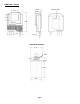
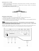
INSTALLATION
Unpack the transmitter carefully. Inspect all units for damage. Report any damage to carrier immediately. Check the
contents against the packing slip and purchase order. Kenco’s SmartSonic Acoustic Wave Transmitters are
manufactured to the highest quality standards. These instruments use electronic components that can be damaged by
static electricity. Make sure that you are properly grounded before starting installation. Insure that all electrical
connections are properly made, and that there are no “floating” connections.
Description Specification
Power Supply 100-230 Vac
Maximum Range 39.4 feet
Minimum Dead Zone 1.3 feet
Maximum Span 38.1 feet
Frequency 50 kHz
Analog 4-20mA
Digital RS-422
Output
Signal
Discrete (5) SPDT Relays
AC 2A @ 220Vac Relay
Ratings
DC 2A @ 30Vdc
Display Graphical LCD User
Interface
Keypad 4 Button
Wave Angle 5º @ 3db
Mounting Connection 1” NPT
Ambient -40ºF to 140ºF Temperature
Range
Process -40ºF to 212ºF
Accuracy ±0.2% of max. range
Resolution 0.04” (1 mm)
Enclosure Material ABS + UV
Transducer Housing Material Polypropylene or PVDF
Transducer Material Glass Reinforced Epoxy
Cable Length 328ft. (std.); 656ft. (opt.)
Electronics 2.4 lbs
Weight
Sensor 1.1 lbs.
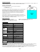
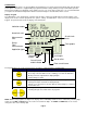
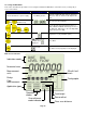
The SmartSonic Transmitters consist of two main components:
• The Electronics
• The Sensor (Transducer)
The transducer contains a piezoelectric crystal that converts an electrical signal
from the electronics, into acoustic (sound) waves. These acoustic waves are
directed through the air toward the process media surface. They are then
reflected off of this surface and returned to the transducer. The piezoelectric
crystal then converts the received waves into an electrical signal which is
analyzed by the electronics.
The time difference between the transmitted wave and the received wave is
proportional to the distance from the face of the transducer to the process media
surface. This distance is used by the electronics to calculate level or open
channel flow in the units selected by the operator.
Process
Media
Air
Acoustic
Waves