KENCO ENGINEERING COMPANY P.O. BOX 470426 TULSA, OK 74147-0426 ● PHONE: (918) 663-4406 FAX: (918) 663-4480 www.kenco-eng.com e-mail: info@kenco-eng.com SMARTSONIC REMOTE ACOUSTIC WAVE LEVEL / OPEN CHANNEL FLOW TRANSMITTER INSTALLATION / OPERATION INSTRUCTIONS TABLE OF CONTENTS 1. 2. 3. 4. 5. 6. 7. 8. 9. 10. 11. 12. 13. 14. GENERAL DESCRIPTION ............................................................. PRINCIPLE OF OPERATION ......................................................... MODEL DESCRIPTION .....
GENERAL DESCRIPTION The SmartSonic Acoustic Wave Transmitter is designed for high accuracy level measurement of a variety of liquids. The SmartSonic Integral can also be used for Open Channel Flow Measurement. PRINCIPLE OF OPERATION The SmartSonic Transmitters consist of two main components: • The Electronics • The Sensor (Transducer) The transducer contains a piezoelectric crystal that converts an electrical signal from the electronics, into acoustic (sound) waves.
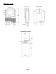
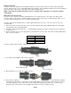
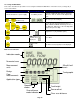
DIMENSIONS - INCHES Mounting Plate 3.26 2.87 3.31 3.15 2.75 9.68 7.87 2.28 Transducer (Sensor) 2.83 1” NPT 0.59 0.55 4.88 2.
MOUNTING GUIDELINES The transmitter must be mounted in such a way, as to avoid the process fluid level from entering the Dead Zone. While the narrow wave diameter of the Kenco Acoustic Wave Transmitters allows you to mount the sensor closer to the vessel wall, than other Ultrasonic transmitters, it is recommended to mount the sensor at least 1.64 feet away from the wall.
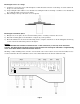
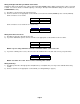
Mounting the Sensor to a Flange 1.) Feed the free end of the sensor cable through the 1” NPT threaded connection on the flange. Feed the cable from the process side of the flange 2.) Keep feeding the cable until the sensor threads are touching the inside of the flange. Screw the sensor threads into the 1” NPT threaded connection on the flange. 3.) Bolt the flange to the top of the tank. Use a soft gasket. Mounting the Transmitter (Electronics) 1.) Drill (2) holes, 2.
Wiring Connections In order to connect the wiring, remove the ribbed faceplate on the front of the electronics, using a 7/64” (3mm) Allen wrench. Ensure that the cover is reinstalled, with the gasket in place, after completing the wiring. Refer to the drawing on the previous page for the location of the wiring connections and cable entries. NOTE: Power must be off when wiring the electronics. Damage and/or injury may occur if power is applied during wiring.
Wiring the Digital and Analog Communication Cables SmartSonic data can be monitored on a PC or PLC via RS-485 (MODBUS RTU) digital communications, when connected to JP22. You can also monitor a 4-20mA output by connecting to JP32 (the 4mA and 20mA settings are discussed in the CALIBRATION section). 1.) Thread the connection wires through aperture C2. 2.) Connect each wire to the appropriate screw terminal at connection block JP22 (MODBUS) and / or JP32 (4-20mA).
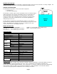
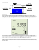
CALIBRATION This section explains how to set up and calibrate the SmartSonic for accurate measurement monitoring using the basic menu options. SmartSonic is supplied with preprogrammed default settings, making it ready for immediate operation. Measurement readings are displayed on the default screen as soon as the unit is powered on. It is recommended that you replace the default tank height value with the actual tank height, as described later in this section.
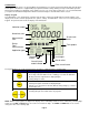
Tank Terminology Dead Zone Dead Zone Air Tank Height SmartSonic Remote ● Maximum 39.4 feet Tank Height SmartSonic Remote ● Minimum 1.3 feet Span Range (4mA to 20mA) Span Process Media SmartSonic Remote ● Maximum 38.1 feet Default Screen As soon as SmartSonic is fully installed and powered on, the LCD displays the default screen.
Accessing the Main Menu This section describes the procedure for accessing the SmartSonic Main Menu. The main screen (see Page #7) is accessed as follows: Press / Action Display Description The SmartSonic takes several seconds to warm-up. During this time various characters Connect SmartSonic to power supply See Wiring Section will turn on and off, and the Tank Graphic will cycle and This is the password display simultaneously Use to enter the password (716) in place of (000).
SETTING MAIN MENU OPTIONS The following functions are available in the SmartSonic Main Menu: Functions Page Setting the Indication Mode 11 Setting the Measurement Units 12 Setting the Relay Values 12 Setting The 20mA and 4mA Values 17 Setting the Open Channel Flow Measurements 17 Setting the Tank Height 17 Setting the Application Type 18 Setting the Operation Modes 18 Setting the Sensor Offset 19 Setting the Scan Distance Values 20 Clearing the Scan Distance Values 21 NOTES: After y
Setting the Measurement Mode This function is used to select the units used for the display. The following measurement options are available: • METER (default), INCH, or FEET: Select one of these options for Level or Distance measurements 3 • M /HR or G.P.M.: Select one of these for Flow measurements After setting the measurement unit, the selected unit flashes on the display whenever you enter numerical values during the setup procedure.
Volume and Totalization should only be configured after setting the Volume/Totalization options in the Additional Features Section later in this manual. The following are the relay setup options: Indication Mode Relay Mode Distance Distance / Level Level Level / Distance Volume Volume Flow Flow / Distance / Level Totalization Flow / Totalization For example, if the SmartSonic is set to FLOW Indication Mode, the relay can be set to Flow, Distance or Level values.
Press / Action Display Description Press ENT when “Relay” is flashing to enter relay setup For example: Cycle between Level, Distance, Flow (see next table), Volume, Totalization (Relay #5 only).
Press / Action Display Description Press ENT when “Relay” is flashing to enter relay setup For example: Cycle between options until it displays FLOW or Press ENT to select the FLOW option or Select the relay number you wish to configure, then press ENT. then The appropriate relay number (Relay #1 in this example), flashes throughout the process of defining the values for the relay and This screen allows you to enter up to (4) digits of High numbers of flow values.
Press / Action Display Description Move to Relay #4, then press ENT. or and Choose Err En to enable error alert; Choose Err dS to disable error alert. Setting Relay #5 for Flow Totalization Pulse You can choose to set Relay #5 for flow totalization pulse or to remain in normal set-up mode. This option enables you to reserve the accumulated value gathered by the unit, by using an external counter. In this way the total value will be reserved even if the unit will be replaced.
Setting the 20mA and 4mA Values SmartSonic enables you to set Distance, Level, Volume or Flow values to be used as 20mA and 4mA settings. The default value for 20mA is the Tank Height (or the maximum Volume value), and the default value for 4mA is 0 (or the minimum Volume value). NOTES: The values for 20 mA and 4 mA must be different, otherwise an Err. 4 message is displayed. Both must also be less than the tank height value, otherwise an Err. 7 message is displayed.
NOTES: Whenever the tank height is required, you should enter the distance from the face of the sensor to the bottom of the tank. In order to obtain accurate measurement results it is most recommended to perform this operation when the tank is empty. For flow measurement, enter the precise flume height. If the entered tank height value is less than a value previously entered for the 4 mA, 20 mA or Relay functions, the value for that function will automatically revert to the default value.
NOTE: STORAGE I and STORAGE II are not suitable for measuring liquids containing foam, since these modes cannot perform signal processing. The operation modes are not relevant for flow applications. If one of the STORAGE I, STORAGE II or PROCESS options is selected when SmartScan is in FLOW application mode, an warning message is displayed and SmartScan reverts to distance mode. You must then reset the unit to flow mode. Press / Action Display Description Move to STORAGE I (flashing).
Setting the Scan Distance Values (False Targets) Up to eight interfering signals (false echoes) can be located by SmartSonic Remote and stored in its memory. The false echoes, which may be caused by obstructions such as a tank agitator or a side wall, can generate false readings and so interfere with the true scanning of the tank contents. Defining interfering signals is done while the tank is empty.
Press / Action Display Description Move to AUTO CAL (flashing). or and Displays while the SmartSonic Remote searches for a False Target simultaneously For Example: Displays the first target. If this is not the distance to the process fluid, or bottom of the tank, press NEXT Wait a few seconds For Example: Displays the next target.
OPEN CHANNEL FLOW MEASUREMENT This section describes how to set the flow measurement parameters for Open Channel Flow measurement. It also covers the flume/weir codes used when selecting the flume or weir of your application. The PARSH.FLUM function in the main menu enables you to select one of the preset flumes/weirs settings for flow measurements.
The flume/weir type code methodology used when setting up open channels is based on three digits: X .(E/U) FF Where: X refers to the particular flume/weir type E/U refers to European or American standard FF refers to the specific flume/weir dimensions Press / Action Display Description Move to PARSH.FLUM (flashing). or 0.U01 Used to select the desired value. See table below to find the desired flow device. Press ENT when finished.
Flumes / Weirs – U.S. Standard (dimensions are in inches unless otherwise indicated) Type 1 (X) – Rectangular Suppressed Sharp-Crested Weir Code (FF) Crest Length 01 12.00 02 18.00 03 24.00 04 30.00 05 36.00 06 48.00 07 60.00 08 72.00 09 96.00 Code (FF) Crest Length 01 12.00 02 18.00 03 24.00 04 30.00 05 36.00 06 48.00 07 60.00 08 72.00 09 96.00 Code (FF) Crest Length 01 12.00 02 18.00 03 24.00 04 30.00 05 36.00 06 48.00 07 60.00 08 72.00 09 96.
Type 4 (X) – V-notch (Triangular) Sharp-Crested Weir Code (FF) V-notch Angle 01 90º 02 60º 03 45º 04 30º 05 22.
Type 7 (X) – H-Flume Code (FF) Flume Size Measurement Point 01 6 1.96 02 9 2.75 03 12 3.54 04 18 5.51 05 24 7.08 06 30 9.05 07 36 11.02 08 54 16.
Flumes / Weirs – European (dimensions are in centimeters unless otherwise indicated) Type 1 (X) – Rectangular Suppressed Sharp-Crested Weir Code (FF) Crest Length 01 20 02 40 03 60 04 80 05 100 06 150 07 200 08 300 Type 2 (X) – Rectangular Contracted Sharp-Crested Weir Code (FF) Crest Length 01 20 02 30 03 40 04 50 05 60 06 80 07 100 08 150 09 200 10 300 Type 3 (X) – Trapezoidal (Cipolletti) Sharp-Crested Weir Code (FF) Crest Length 01 30 02 45 03 60 04 80 0
Type 4 (X) – V-notch (Triangular) Sharp-Crested Weir Code (FF) V-notch Angle 01 90º 02 60º 03 53.8º 04 45º 05 30º 06 28.4º 07 22.5º British Standard 08 90º 09 45º 10 22.
Type 7 (X) – Palmer-Bowlus Flume Code (FF) Conduit Diameter (in) 01 6 02 8 03 10 04 12 05 15 06 18 07 21 08 24 09 27 10 30 Type 8 (X) – H-Flume Code (FF) Flume Size (in) Measurement Point (cm) 01 6 5 02 9 7 03 12 9 04 18 14 05 24 18 06 30 23 07 36 54 28 08 41 Type 9 (X) – Neyrpic-Venturi Flume / Long Base Weir Code (FF) Flume Type Code (FF) 01 1253AX 06 Flume Type 1253C 02 1253AY 07 1253D 03 1253AZ 08 1253E 04 1253A 09 1253F 05 1253B Long B
ADDITIONAL FEATURES This section describes the functions available in SmartSonic Remote's additional menu. The additional menu functions enable you to calibrate SmartScan to perform the following tasks: • Display Values in volume format. • Display Values as a total accumulative value for flow. • Calculate volume for different tank types. • Calculate flow measurements for custom flumes. • Calculate results in alternative measurement units.
Functions Page Pr 0 – Selecting an Indication Mode 31 Pr 1 – Manually Inserting Strapping Table Values 32 Pr 2 – Semi-automatic Inserting Strapping Table Values 33 Pr 3 – Entering a Coefficient for Readings 34 Pr 4 – Erasing Strapping Table Values 34 Pr 5 – Configuring Height for a Cone Bottom Tank 35 Pr 6 – Defining the 4-20mA Error Signal (3.
Manually Inserting Strapping Table Values The Pr 1 function enables you to manually create a strapping table of distance points for either volume calculations or custom flume measurements. The strapping table is used for manual insertion of distance/volume values when IND 1 was selected as the value for Pr 0, Manual insertion is applicable when the ratio between the distance and volume of the tank is known or for applications such as custom-shaped tanks.
Semi-automatic Inserting Strapping Table Values The Pr 2 function enables you to create a strapping table for distance/volume values using distance values measured automatically by SmartScan, rather than entered manually as described in the previous section. This method enables more accurate volume indications than the manual method, but entails slower calibration due to the need for additional instruments, such as a flow meter.
Entering a Coefficient for Readings The Pr 3 function enables you to enter a coefficient value, K, which can be used for three different options.
Configuring Height for a Cone Bottom Tank The Pr 5 function enables you to enter the cone height for tanks that have a conical base. This may be required if you are unable to mount the sensor at the center of the tank, or if the cone is causing false echoes and consequently faulty measurements. The entered cone height value can be from a minimum of 000.000 (the default value) up to a maximum of half the tank height value. NOTE: An Err.
Defining the 4-20mA Error Signal (3.7mA or 22mA) The Pr 6 function allows you to define whether the following signal error indications Near Zone and Lost Echo will be active when the current output reaches 22mA or 3.7mA. The SmartScan default setting enables 22mA analog current and error messages to appear on its LCD display. Near Zone - Whenever the level is below the defined Dead Zone SmartSonic Remote's LCD.
TROUBLESHOOTING This chapter describes the error messages displayed when an illegal value is entered for a SmartSonic Remote function. If an illegal value is entered, the appropriate error message is displayed flashing while the level of the tank graphic on the bottom-right of the screen moves up from 0 to 100%. The numerical area then displays , enabling you to enter a new value for the function.