
User guide

Page 5
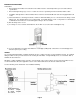
Wiring Connections
Before starting installation procedures in hazardous areas, insure that all power sources have been turned off and locked
out. “Live” electrical circuits can ignite flammable gasses and dusts. Do not apply more than 28Vdc to the transmitter, as
this may damage the instrument.
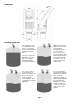
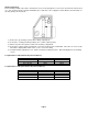
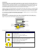
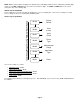
1.) Remove the (4) retaining screws from the wiring compartment.
2.) Connect the conduit (preferably flexible) to the ½” NPT conduit opening.
3.) Pull the loop wires through the conduit, into the wiring compartment.
4.) Connect the negative lead to Terminal #1; connect the positive lead to Terminal #2. If the wires are reversed, the
transmitter’s display will be blank. If this occurs, reverse the wiring.
5.) Install the wiring compartment cover. Make sure that the O-Ring is in place. Attach and tighten the (4) retaining
screws.
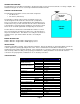
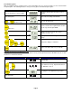
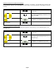
Loop Resistance Table (Intrinsically Safe Installation)
Power Supply Voltage Minimum Resistance Maximum Resistance
12 - 18 Vdc 41 Ω 220 Ω
18.1 - 24 Vdc 41 Ω 310 Ω
24.1 - 28 Vdc 68 Ω 520 Ω
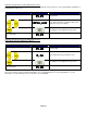
Loop Resistance Table (Non-Intrinsically Safe Installation)
Power Supply Voltage Minimum Resistance Maximum Resistance
12 Vdc 0 Ω 50 Ω
12.1 - 15 Vdc 0 Ω 220 Ω
15.1 - 24 Vdc 41 Ω 610 Ω
24.1 - 28 Vdc 68 Ω 820 Ω