
Instruction Manual

OIL LEVEL CONTROLLERS WITH –9U (Universal adapter for 512 Oil Level Controllers), -12 (Pole mounted adapter) AND –FS
OPTIONS
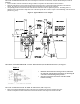
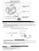
• Set the controller so that the centerline of the sight window corresponds to the desired oil level in the crankcase.
• Mount the controller close to the crankcase and connect the hose from the ¾” outlet located on the controller to the crankcase.
NOTE: The outlet port on the oil level controller must be located below the oil level in the crankcase.
• An equalizing line must be used between the controller and crankcase in order to equalize the pressure. The tubing must be a
minimum of 1/2” I.D. and must be kept under 2 feet. DO NOT loop this line. It must be trap free and self draining, with a downward
pitch flow by gravity.
OIL LEVEL CONTROLLER WITH
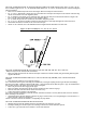
–11 AND –11-FS OPTION (for Mechanical Lubricators): See Figure 3
OIL LEVEL CONTROLLER WITH
–14 AND –14 –FS OPTION (White Compressor)
• Remove the triangular blind flange located on the compressor and mount the controller assembly in its place.
NOTE: It is important to install a drain line between the drain outlet of the compressor and the controller.
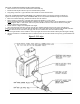
•
Drill holes in the lubricator housing as shown, and mount
the controller with the inlet located on the top side using the
seal washers and mounting bolts provided.
• Place the seal washers between the controller and the
lubricator housing.
Figure 3
Fi
g
ure 2: T
yp
ical Mount of –9U Ada
p
ter
KENCO TULSA