MinarcMig Evo 170, 200 Operating manual Käyttöohje EN FI Bruksanvisning SV Bruksanvisning NO Brugsanvisning DA Gebrauchsanweisung DE Gebruiksaanwijzing NL Manuel d’utilisation FR Manual de instrucciones ES Instrukcja obsługi PL Инструкции по эксплуатации RU Manual de utilização PT Manuale d’uso 操作手册 IT ZH
OPERATING MANUAL English © Kemppi Oy / 1340
CONTENTS 1. Preface.................................................................................................................. 3 General. ............................................... . . . . . . . . . . . . . . . . . . . . . . . . . . . . . . . . . . . . . . . . . . . . . . . . . . . . . . . . . . . . . . . . . . . . . . . . . . . . . . . . . . . . . . . . 3 Product introduction. .................... . . . . . . . . . . . . . . . . . . . . . . . . . . . . . . . . . . . . . . . . . . . . . . . . .
1. PREFACE 1.1 General Congratulations on choosing MinarcMig Evo welding equipment. Used correctly, Kemppi p°roducts can significantly increase the productivity of your welding, and provide years of economical service. This operating manual contains important information on the use, maintenance and safety of your Kemppi product. The technical specifications of the equipment can be found at the end of the manual. Please read the manual carefully before using the equipment for the first time.
You can use steel (solid or cored wire), stainless steel, aluminium and CuSi as filler wire in the machine. The steel wire can be 0.6 mm, 0.8 mm, 0.9 mm or 1.0 mm thick, but the machine’s welding properties are optimum with a steel wire of 0.8 mm diameter. The stainless steel wire can be 0.8 mm, 0.9 mm or 1.0 mm in diameter, the aluminium wire 1.0 mm and CuSi wire 0.8, 0.9 and 1.0 mm. 1.2.
2.2 Positioning and location of the machine Place the machine on a firm, dry and level surface. Where possible, do not allow dust or other impurities to enter the machines cooling air flow. Preferably site the machine above floor level; for example on a suitable carriage unit. Notes for positioning the machine • The surface inclination should not exceed 15 degrees. • Ensure the free circulation of the cooling air.
2.6 Cable connections Connection to the mains The machine is fitted with a 3 m long supply voltage cable and plug. Connect the supply voltage cable to the mains. Should you need to fit an alternative plug or mains cable, ensure installation is completed by an authorised electrician. NOTE! The fuse size needed is 16 A delayed. If you use an extension cable, its cross-sectional area should be at least as large as the machines supply cable (3 x 1.5 mm²). It is recommended to use 3 x 2.5 mm² extension cable.
Shielding gas Shielding gas is used for replacing air around the welding arc. For steel wires, use CO₂ (carbon dioxide) or a mixture of Ar (argon) and CO₂ for shielding gas. Welding performance will be improved when using mixed gas products. For stainless steel wires, use mixture of Ar and CO₂ (2 %), and for aluminium and CuSi wires, use pure argon. The required flow rate of the shielding gas is determined by the thickness of the welded sheet and the used welding power. The machine is delivered with a 4.
2.7 Filler wire The machine is delivered with the welding gun connected to the positive pole (+) making it suitable for welding with solid steel, stainless steel, aluminium and CuSi filler wires without extra adjustments. 2.7.1 Changing the feed roll groove When the machine leaves factory, the feed roll groove is set for welding with filler wires of 0.8–1.0 mm diameter. The feed roll groove must be changed, if you use 0.6 mm thick filler wire. Changing the feed roll groove 5., 8. 6. EN 1., 9. 3. 2., 4.
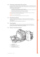
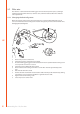
2.7.2 Loading and threading the filler wire 1., 10. 1. Open the filler wire cabinet door by pressing the orange door latch button and installing the filler wire spool in such a way that it rotates counter clockwise. You can use either a 5 kg (diameter 200 mm) or 1 kg (100 mm) filler wire spool with MinarcMig Evo by adding or removing the 200 mm spool adapter. 5 kg EN 2. 1 kg 2. 2. 3. 4. 5. Attach the wire spool friction plate, lock and secure the spool.
7. 9. 5., 8. 6. 7. 8. EN 9. 10. 11. 12. Open the pressure control arm which then opens the feed mechanism. Thread the filler wire through the wire guide to the wire liner inside the gun cable. Close the feed gear and secure it with the pressure control arm. Make sure that the filler wire runs in the feed roll groove. Adjust the filler wire compression with the pressure control arm, no higher than to the middle of the scale.
2.8 Controls and indicator lights MinarcMig Evo 170 control panel 4. 5. 6. 3. EN 2. U 1. 2. 3. 4. 5. 6. W006095 1. Wire feed speed control Welding voltage control Dynamics selection control Standby indicator light Overheating indicator light Display Wire feed speed and welding voltage values are set and adjusted independently. Guide parameter values can be viewed on page 15 of this manual.
MinarcMig Evo 200 control panel 3. 4. 5. 7. 6. EN 1. 2. S U Machine's control panel in automatic mode 1. Welding power control (automatic mode) OR Wire feed speed control (manual mode) 2. Arc length trimmer (automatic mode) OR Welding voltage control (manual mode) 3. Standby indicator light 4. Overheating indicator light 5. Mode selection button 6. Material selection button (automatic mode) 7.
2.8.1 Display in automatic mode 3. 4. 1. 5. 6. 2. 7. Machine display in automatic mode 1. Material thickness 2. Visual material thickness and weld shape indicator 3. Operating mode reference 4. Material selection 5. Shielding gas and wire diameter recommendation 6. Wire feed graphic 7. Welding values: Wire feed speed, welding voltage and welding current MinarcMig Evo 200 automatically sets the machine based on your input selections for plate thickness in mm, weld shape and material type.
2.8.3 Arc length trimmer in automatic mode The arc length/weld shape/voltage trimmer adjusts the length of the arc, either shorter or longer, and affects the welding temperature. A shorter arc is colder and a longer one hotter. The arc length trimmer also affects the arc’s welding properties and influences weld spatter with different combinations of filler wire diameters and shielding gases. The trimmer range is -9...0...9: negative values shorten and positive values lengthen the arc.
Arc dynamics In Manual mode you can select from two different arc dynamics settings. Press Manual mode button (Arc Dynamics control on MinarcMig 170 model) once to pre-select either arc dynamic value I or value II. Changing between setting I and setting II will adjust the short circuit characteristics to suit different welding applications. 2.8.5 Adjustments in manual mode EN In manual mode, the wire feed speed and welding voltage are both adjusted separately.
EN Having checked that the MinarcMig Evo is prepared in the correct way for the welding task ahead, and that you are wearing the necessary protective equipment, you are ready to commence welding. MIG/MAG welding can be performed down hand, vertically and overhead: either right to left (Right handed operators) or left to right (left handed operators) First, present the welding gun nozzle to a practice work piece.
2.10 Using the shoulder strap 1. 2. 3. 4. EN Using and fixing the shoulder strap The machine is delivered with a fabric shoulder strap and metal clip set. The shoulder strap can be used as a convenient and comfortable way to transport both the machine and cables set. There are two identical metal clips. Fix one clip to each of the metal lifting eyes, located at the top of the machine. Adjust the shoulder strap to a comfortable length. The machine can now be carried.
3.2 Maintenance of the wire feed mechanism Parts of the welding gun and wire liner 9 EN 1 2 3 4 5 6 7 8 9 10 11 9580101 9591010 9876634 9876635 9876633 9876636 9580173 9591079 4153040 4307650 4307660 8 7 3 4 5 6 2 1 0.6 mm 0.8 mm 0.9 mm 1.0 mm 45° 10, 11 0.6–1.0 mm (Fe, CuSi) 0.6–1.0 mm (Ss, Al) Service the wire feed mechanism at least every time the spool is changed. • Check the wear of the feed roll groove and change the feed roll when necessary.
5. 6. 7. 3.3 Tighten the wire guide in place with the mounting nut. Cut the wire guide 2 mm from the mounting nut and file the sharp edges of the cut round. Reattach the gun in place and tighten the parts to spanner tightness.
4. ORDERING NUMBERS includes gun, cables, gas hose and shoulder strap MinarcMig Evo 170 includes gun, cables, gas hose and shoulder strap MinarcMig Evo 170 AU includes gun, cables, gas hose and shoulder strap MinarcMig Evo 170 (Denmark) includes gun, cables, gas hose and shoulder strap MinarcMig Evo 200 includes gun, cables, gas hose and shoulder strap MinarcMig Evo 200 AU includes gun, cables, gas hose and shoulder strap MinarcMig Evo 200 (Denmark) 3m Welding gun MMG22 3m Earthing cable and clamp 4.
5. TECHNICAL DATA MinarcMig Evo 170 Connection voltage Connection voltage (AU) Rated power at max.
MinarcMig Evo 200 Connection voltage Connection voltage (AU) Rated power at max.
KEMPPI OY Kempinkatu 1 PL 13 FIN-15801 LAHTI FINLAND Tel +358 3 899 11 Telefax +358 3 899 428 export@kemppi.com www.kemppi.com KEMPPI (UK) Ltd Martti Kemppi Building Fraser Road Priory Business Park BEDFORD, MK44 3WH UNITED KINGDOM Tel +44 (0)845 6444201 Telefax +44 (0)845 6444202 sales.uk@kemppi.com Kotimaan myynti: Tel +358 3 899 11 Telefax +358 3 734 8398 myynti.fi@kemppi.com KEMPPI FRANCE S.A.S.