
Instruction Manual

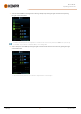
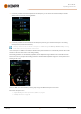
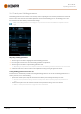
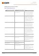
Table Of Contents
- 1. General
- 2. Installation
- 2.1 Installing power source mains plug
- 2.2 Installing cooling unit (optional)
- 2.3 Installing equipment on cart (optional)
- 2.4 Connecting welding gun
- 2.5 Installing earth return cable
- 2.6 Installing remote control (optional)
- 2.7 Installing and replacing feed rolls
- 2.8 Installing and replacing wire guide tubes
- 2.9 Installing and changing wire
- 2.10 Installing gas bottle and testing gas flow
- 2.11 How to get welding programs
- 3. Operation
- 3.1 Preparing welding system for use
- 3.2 Calibrating welding cable
- 3.3 Using control panel
- 3.3.1 Control panel: Home view
- 3.3.2 Control panel: Weld Assist
- 3.3.3 Control panel: Channels
- 3.3.4 Control panel: WPS view
- 3.3.5 Control panel: Welding parameters
- 3.3.6 Control panel: Weld history
- 3.3.7 Control panel: Info view
- 3.3.8 Control panel: Device settings
- 3.3.9 Control panel: Applying welding programs
- 3.3.10 Control panel: Weld data view
- 3.4 Additional guidance to functions and features
- 3.5 Pulse welding
- 3.6 Wireless connection (WLAN)
- 3.7 Using remote control
- 3.8 Changing welding polarity
- 3.9 Lifting equipment
- 4. Maintenance
- 5. Technical data

Master M 358
Operating manual - EN
Dynamics
-10.0 ... +10.0, step 0.2
Default = 0
Controls the short circuit behavior of
the arc. The lower the value the
softer the arc, the higher the value
the rougher the arc.
(Not available with MAX Cool and
MAX Speed.)
Crater fill
ON/OFF When welding with high power, a crater
is usually formed at the end of the weld.
The Crater fill function decreases the
welding power / wire feed speed at the
end of the welding job so that the crater
can be filled using a lower power level.
With MIG process, Crater fill duration,
wire feed speed and voltage are preset
by the user.
When the wire feed speed is less than 5
m/min, the adjustment step is 0.05 and
when the wire feed speed is 5 m/min or
more, the adjustment step is 0.1.
For 1-MIG process, refer to the 1-MIG
parameter table.
- Crater filltime
0.1 ... 10.0 s, Auto, step 0.1
Default = 1.0 s
- Crater fill wire feed speed
0.70 ... 25.0 m/min, Auto, step 0.05 or 0.1
Default = 5 m/min
- Crater fill voltage
8 ... 45 V, Auto, step 0.1 V
Default = 18V
Post current
-30 ... +30 Post current setting affects the wire
length at the weld end, for example to
prevent the wire from stopping too close
to the weld pool. This also enables the
optimum wire length for the start of the
next weld.
Wire feed end step (WF end step)
OFF/ON
Default = OFF
Wire feed end step feature prevents the
filler wire from sticking to the contact tip
when the welding ends.
Post gas
0.0 ... 9.9 s, Auto, step 0.1
0.0 = OFF
Welding function that continues the
shielding gas flow after the arc has extin-
guished. This ensures that the hot weld
does not come into contact with air after
the arc is extinguished, protecting the
weld and also the electrode. Used for all
metals. Especially stainless steel and
titanium require longer post gas times.
© Kemppi
46
1921980 / 2242