
Instruction Manual

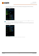
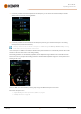
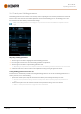
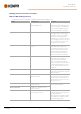
Table Of Contents
- 1. General
- 2. Installation
- 2.1 Installing power source mains plug
- 2.2 Installing cooling unit (optional)
- 2.3 Installing equipment on cart (optional)
- 2.4 Connecting welding gun
- 2.5 Installing earth return cable
- 2.6 Installing remote control (optional)
- 2.7 Installing and replacing feed rolls
- 2.8 Installing and replacing wire guide tubes
- 2.9 Installing and changing wire
- 2.10 Installing gas bottle and testing gas flow
- 2.11 How to get welding programs
- 3. Operation
- 3.1 Preparing welding system for use
- 3.2 Calibrating welding cable
- 3.3 Using control panel
- 3.3.1 Control panel: Home view
- 3.3.2 Control panel: Weld Assist
- 3.3.3 Control panel: Channels
- 3.3.4 Control panel: WPS view
- 3.3.5 Control panel: Welding parameters
- 3.3.6 Control panel: Weld history
- 3.3.7 Control panel: Info view
- 3.3.8 Control panel: Device settings
- 3.3.9 Control panel: Applying welding programs
- 3.3.10 Control panel: Weld data view
- 3.4 Additional guidance to functions and features
- 3.5 Pulse welding
- 3.6 Wireless connection (WLAN)
- 3.7 Using remote control
- 3.8 Changing welding polarity
- 3.9 Lifting equipment
- 4. Maintenance
- 5. Technical data

Master M 358
Operating manual - EN
Welding parameters and feature descriptions
MIG and 1-MIG welding parameters
The parameters listed here are available for adjustment with the MIG and 1-MIG processes.
Parameter Parameter value Description
Process
MIG, 1-MIG, Pulse, DPulse, MAX Cool,
MAX Speed, MAX Position
This MIG welding process selection
depends on the active welding program.
For more information on the additional
processes, refer to "Additional guidance
to functions and features" on page56.
Trigger logic
2T, 4T Welding guns can have several altern-
ative trigger operation modes (trigger
logics). Most common are 2T and 4T. In
2T mode you hold the trigger down
while welding. In 4T mode you press and
release the trigger to start or to stop weld-
ing. For more information, refer to "Trig-
ger logic functions" on page56.
Pre gas
0.0 ... 9.9 s, Auto, step 0.1
0.0 = OFF
Welding function that starts the shielding
gas flow before the arc ignites. This
ensures that the metal does not come
into contact with air at the start of the
weld. Time value is preset by the user.
Used for all metals, but especially for
stainless steel, aluminum and titanium.
Creep start
10...90 %, Auto, step 1 The Creep start function defines the wire
feed speed before the welding arc
ignites, that is, before the filler wire
comes in contact with the workpiece.
When the arc ignites, the wire feed speed
is automatically switched to the normal
user-set speed. The Creep start function
is always on.
Touch Sense Ignition
AUTO/ON/OFF Touch Sense Ignition (TSI) delivers min-
imum spatter and stabilizes the arc imme-
diately after ignition.
Wire feed speed
0.50 ... 25 m/min, step 0.05 or 0.1
Default = 5.00 m/min
Wire feed speed adjustment. When the
wire feed speed is less than 5 m/min, the
adjustment step is 0.05 and when the
wire feed speed is 5 m/min or more, the
adjustment step is 0.1.
Wire feed speed min
Min/Max = 0.5 ... 25 m/min, step 0.1
Default = 0.5 m/min
Minimum and maximum limits for the
wire feed speed adjustment.
Wire feed speed max
Min/Max = 0.5 ... 25 m/min, step 0.1
Default = 25 m/min
Voltage
Min/Max = According to welding equip-
ment specifications, step 0.1
Welding voltageadjustment and the min-
imum and maximum limits for the weld-
ing voltage adjustment.
These parameters are available for adjust-
ment in MIG only. In 1-MIG the voltage is
defined by welding program.
© Kemppi
45
1921980 / 2242