
Instruction Manual

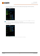
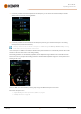
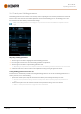
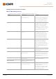
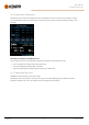
Table Of Contents
- 1. General
- 2. Installation
- 2.1 Installing power source mains plug
- 2.2 Installing cooling unit (optional)
- 2.3 Installing equipment on cart (optional)
- 2.4 Connecting welding gun
- 2.5 Installing earth return cable
- 2.6 Installing remote control (optional)
- 2.7 Installing and replacing feed rolls
- 2.8 Installing and replacing wire guide tubes
- 2.9 Installing and changing wire
- 2.10 Installing gas bottle and testing gas flow
- 2.11 How to get welding programs
- 3. Operation
- 3.1 Preparing welding system for use
- 3.2 Calibrating welding cable
- 3.3 Using control panel
- 3.3.1 Control panel: Home view
- 3.3.2 Control panel: Weld Assist
- 3.3.3 Control panel: Channels
- 3.3.4 Control panel: WPS view
- 3.3.5 Control panel: Welding parameters
- 3.3.6 Control panel: Weld history
- 3.3.7 Control panel: Info view
- 3.3.8 Control panel: Device settings
- 3.3.9 Control panel: Applying welding programs
- 3.3.10 Control panel: Weld data view
- 3.4 Additional guidance to functions and features
- 3.5 Pulse welding
- 3.6 Wireless connection (WLAN)
- 3.7 Using remote control
- 3.8 Changing welding polarity
- 3.9 Lifting equipment
- 4. Maintenance
- 5. Technical data

Master M 358
Operating manual - EN
3.3.5 Control panel: Welding parameters
The Welding parameters view includes a start and stop curve for adjusting the most essential parameters for a weld. The
bottom section of the view lists the available adjustments for the selected welding process. The welding process selec-
tion is based on the active memory channel and its settings.
Many of the welding parameters are welding process specific and are visible and available for adjustment accord-
ingly.
Adjusting welding parameters
1. Turn the right control knob to highlight the desired welding parameter.
2. Press the right control knob to select the welding parameter for adjustment.
3. Turn the right control knob to adjust welding parameter value.
>> Depending on the parameter to be adjusted, refer also to the Welding parameters table below for more details.
4. Confirm the new value / selection and close the adjustment view by pressing the right control knob.
Saving welding parameters for later use
A work channel is automatically created for the changed welding parameters. To save the set welding parameters on a
memory channel, do one of the following:
• Quick active channel option:Keep the Channels shortcut button pressed for approximately 2 seconds.
>> This will save the parameter settings onto the currently active channel replacing its previous parameter set-
tings.
• Channels view option:Go to the Channels view and save the parameter settings onto a new channel.
>> Refer to "Control panel: Channels" on page39 for more information.
© Kemppi
44
1921980 / 2242