
Instruction Manual
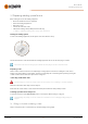
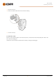
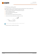
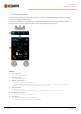
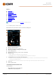
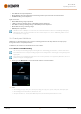
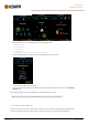
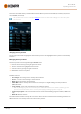
Table Of Contents
- 1. General
- 2. Installation
- 2.1 Installing power source mains plug
- 2.2 Installing cooling unit (optional)
- 2.3 Installing equipment on cart (optional)
- 2.4 Connecting welding gun
- 2.5 Installing earth return cable
- 2.6 Installing remote control (optional)
- 2.7 Installing and replacing feed rolls
- 2.8 Installing and replacing wire guide tubes
- 2.9 Installing and changing wire
- 2.10 Installing gas bottle and testing gas flow
- 2.11 How to get welding programs
- 3. Operation
- 3.1 Preparing welding system for use
- 3.2 Calibrating welding cable
- 3.3 Using control panel
- 3.3.1 Control panel: Home view
- 3.3.2 Control panel: Weld Assist
- 3.3.3 Control panel: Channels
- 3.3.4 Control panel: WPS view
- 3.3.5 Control panel: Welding parameters
- 3.3.6 Control panel: Weld history
- 3.3.7 Control panel: Info view
- 3.3.8 Control panel: Device settings
- 3.3.9 Control panel: Applying welding programs
- 3.3.10 Control panel: Weld data view
- 3.4 Additional guidance to functions and features
- 3.5 Pulse welding
- 3.6 Wireless connection (WLAN)
- 3.7 Using remote control
- 3.8 Changing welding polarity
- 3.9 Lifting equipment
- 4. Maintenance
- 5. Technical data

Master M 358
Operating manual - EN
3.2 Calibrating welding cable
The welding cable resistance can be measured using the built-in cable calibration function without an additional meas-
urement cable. This calibration function is available only in MIG operation mode.
1. Connect the earth return cable between the welding device and work piece.
2. Remove the welding gun gas nozzle.
3. Connect the welding gun to the welding device.
4. Turn the welding device on.
5. On the control panel, go to settings and enable cable calibration.
6. Touch the cleaned work piece briefly with the welding gun contact tip.
There is no need to press the trigger. Trigger function is disabled at this stage.
7. Using the control panel, confirm the measured values.
© Kemppi
35
1921980 / 2242