
Instruction Manual
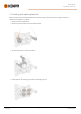
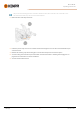
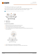
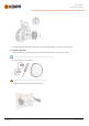
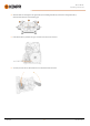
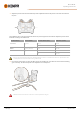

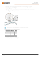
Table Of Contents
- 1. General
- 2. Installation
- 2.1 Installing power source mains plug
- 2.2 Installing cooling unit (optional)
- 2.3 Installing equipment on cart (optional)
- 2.4 Connecting welding gun
- 2.5 Installing earth return cable
- 2.6 Installing remote control (optional)
- 2.7 Installing and replacing feed rolls
- 2.8 Installing and replacing wire guide tubes
- 2.9 Installing and changing wire
- 2.10 Installing gas bottle and testing gas flow
- 2.11 How to get welding programs
- 3. Operation
- 3.1 Preparing welding system for use
- 3.2 Calibrating welding cable
- 3.3 Using control panel
- 3.3.1 Control panel: Home view
- 3.3.2 Control panel: Weld Assist
- 3.3.3 Control panel: Channels
- 3.3.4 Control panel: WPS view
- 3.3.5 Control panel: Welding parameters
- 3.3.6 Control panel: Weld history
- 3.3.7 Control panel: Info view
- 3.3.8 Control panel: Device settings
- 3.3.9 Control panel: Applying welding programs
- 3.3.10 Control panel: Weld data view
- 3.4 Additional guidance to functions and features
- 3.5 Pulse welding
- 3.6 Wireless connection (WLAN)
- 3.7 Using remote control
- 3.8 Changing welding polarity
- 3.9 Lifting equipment
- 4. Maintenance
- 5. Technical data

Master M 358
Operating manual - EN
3. If not already, connect the welding gun to the device (refer to "Connecting welding gun" on page18).
4. Connect the gas hose to the welding device.
5. Open the gas bottle valve.
6. Press the gas test button (*) to test and adjust the gas flow. Use either the built-in rotameter or an external flow
meterand regulator for measuring and adjustment.
The gas test time is 20 seconds by default. The time can be changed in the control panel.
Recommended gas flow rates (for general guidance only):
TIG* MIG**
Argon
5...15 l/min 10...25 l/min
Helium
15...30 l/min -
Argon + 18-25% CO2
- 10...25 l/min
CO2
- 10...25 l/min
* Depending on the gas nozzle size.
** Depending on the gas nozzle size and welding current.
© Kemppi
30
1921980 / 2242