FastMig X 350MV Operating manual EN Brugsanvisning NO Manual de instrucciones ES Manual de utilização PT MENU CHANNEL X37
OPERATING MANUAL English
CONTENTS 1. Introduction........................................................................................................ 3 General. ............................................... . . . . . . . . . . . . . . . . . . . . . . . . . . . . . . . . . . . . . . . . . . . . . . . . . . . . . . . . . . . . . . . . . . . . . . . . . . . . . . . . . . . . . . . . 3 About FastMig X 350MV............... . . . . . . . . . . . . . . . . . . . . . . . . . . . . . . . . . . . . . . . . . . . . . . . . . . . . . .
1. INTRODUCTION 1.1 General Congratulations on choosing the FastMig X 350MV welding equipment. Used correctly, Kemppi products can significantly increase the productivity of your welding, and provide years of economical service. This operating manual contains important information on the use, maintenance and safety of your Kemppi product. The technical specifications of the equipment can be found at the end of the manual.
2. INSTALLATION 2.1 Before use The product is packed in specially designed transport cartons. However, before use always make sure the products have not been damaged during transportation. Check also that you have received the components you ordered and the corresponding instruction manuals. Product packaging material is recyclable. NOTE! When moving the welding machine, always lift it from the handle, never pull it from the welding gun or other cables.
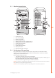
2.3 Machine introduction 1. CHANNEL 10. 3. 2. 6,3A 4. 11. 7. 6. 5. 1. 2. 3. 4. 5. 6. 7. 8. 9. 10. 11. 2.4 8. V 9. EN Control panel X 37 Main switch (ON/OFF) Power on pilot lamp Overheating pilot lamp Welding cable connection, negative pole (–) Welding cable connection, positive pole (+) Control cable connection Fuse (delayed 6.
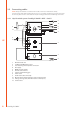
2.5 Connecting cables NOTE! Always check before use that the mains cable, earth return cable and its clamp, interconnection cable and shielding gas hose are in a serviceable condition. Ensure that connectors are correctly fastened. Lose connectors can impair welding performance and damage connectors. 2.5.1 Liquid-cooled system: FastMig X 350MV + WFX + Cool X 5. 11. 4. V 6. 1. 12. 7. EN 8. 10. V 2. 3. 9. 1. 2. 3. 4. 5. 6. 7. 8. 9. 10. 11. 12.
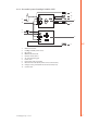
2.5.2 Air-cooled system: FastMig X 350MV + WFX 4. 10. 3. V 5. 1. 11. 6. 7. 9. V 2. 8. 1. 2. 3. 4. 5. 6. 7. 8. 9. 10. 11.
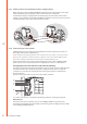
2.5.3 Cable positions for multiple machine configurations When using two or more FastMig X 350MV units working on the same work piece, the right positioning of voltage sensing cable and the earth return cable is important. In order for the voltage sensing function to work properly, the earth return cable and the voltage sensing cable for each FastMig X 350MV unit should be connected close to each other and away from other units’ cables (see the pictures below). EN 2.5.
2.5.5 Cables Kemppi always recommend the use of high quality copper cables with a suitable crosssectional area. Cable size should be selected depending on the intended welding application. 50 mm² copper cables may be used for low duty work in basic or synergic 1-MIG. However, using pulsed MIG/MAG process, longer cables, or higher welding power increase the voltage loss, and therefore smaller cross sectional interconnection cables and earth return cables will restrict the welding performance of your machine.
3. OPERATION CONTROL 3.1 Main switch I/O When you turn the on/off switch into position I, the pilot warning lamp is illuminated and the machine is ready for use. Always turn the machine on and off with the power source mains switch. Never use the mains plugs as a switch. 3.2 Pilot lamps The pilot lamps of the machine report its operational state: When the green pilot lamp is on, it indicates that the machine is switched on and ready for use.
4. CONTROL PANEL X 37 FastMig X 350MV power source features X 37 control panel with a clear and logical LCD menu display. The menu allows the operator to refine, adapt and manage the arc process and system function before, during and after welding. The following information details control panel layout, button functions, operation and setup. The menu options and their descriptions are listed for each menu command. 4.1 Layout and button functions 1. 2. 7. 8. 4. EN CHANNEL INFO F1 3.
Language Select Feeder (WF#) MMA/CC/CV Mode Select your menu language Select another parallel wire feeder as a setup target Activate MMA welding, or use CC or CV mode for ArcFeed or MasterTig LT 250 4. Adjustment knob Turn the knob to change the value of the selected parameter. In MMA/CV/CC mode when panel is in default initial view (channel information), knob can be used to adjust current (MMA and CC) or voltage (CV). 5.
available for MMA/CC/CV use. To define a new welding job, you need to make the necessary welding parameter selections and then save them to a memory channel of your choice. When you want to use these settings, you simply select the corresponding memory channel number on the power source or wire feeder control panel and start welding. Only the most often used controls are available in the wire feeder control panel, making welding easy and convenient.
4.3 Welding parameters MIG WFSpeed WFS-Max WFS-Min Voltage VoltageMax VoltageMin Dynamics EN 0.7…25 m/min Sets the wire feed speed. Changes by steps of 0.05, when WFSpeed < 5 m/min, and by 0.1, when WFSpeed > 5 m/min Sets the limit for maximum WFSpeed Sets the limit for minimum WFSpeed 8…50 V Step: 0.1 Controls the length of the arc Sets the limit for maximum voltage value Sets the limit for minimum voltage value -9…+9 Factory setting is 0 Controls the short circuit behaviour of the arc.
DOUBLE PULSE MIG WFSpeed WFS-Max WFS-Min FineTuning 0.7…25 m/min * Sets the wire feed speed. Changes by steps of 0.05, when WFSpeed < 5 m/min, and by 0.1, when WFSpeed > 5 m/min Sets the limit for maximum WFSpeed Sets the limit for minimum WFSpeed -9.0…+9.0 Factory setting is 0.0 Adjusts the base current of the curve (arc length) in ( = curve point) certain limits FineTuningMax -9.0…+9.0 FineTuningMin -9.0…+9.0 -9…+9 Dynamics Step: 0.5 Sets the limit for maximum arc length Step: 0.
MMA PROCESSES Current CurrentMax CurrentMin ArcForce 14…350 A Welding current 14…350 A Set the limit for maximum current value 14…350 A Set the limit for minimum current value -9…+9 Factory setting is 0 Controls the short circuit behaviour of the arc. The lower the value the softer the arc is. The higher the value the rougher the arc is.
Crater 4T Timer On, OFF Factory setting is OFF ON: if 4T is selected, crater filling will last at least time that has been adjusted by CraterTime or as long as trigger is pressed. OFF: if 4T is selected, crater filling will last as long as trigger is pressed. Creep Start 10…99 % Step: 1 OFF, CURVE (OFF=100%) Factory setting is CURVE CURVE means that the creep start value comes from welding program. StartPower -9…+9 Factory setting is 0 Adjusts arc ignition.
Info Shows following information about the selected device. Device name: DevSW: Unit software version. SysSW: System software version (base software version). BootSW: Boot software version. SW Item: Software item number (IFS code). Serial: Device serial number. Prog: Programmer name Date: Programming time and date. Restore Settings User 1 (one of ten users) Channel: Selected user can restore to his backup memory channels one by one. Other users’ memory channels remain untouched.
Control * USER, PANEL, REMOTE, GUN. RemoteAutoRecog ON, OFF. Factory settings is USER This setting affects the XF 37 (or XF 38) control panel remote control unit selection. USER: User can select the remote control device at XF 37 (or XF 38) panel PANEL: Selection is locked to PANEL, and user can not select the remote device at XF 37 panel. REMOTE: Selection is locked to HAND REMOTE device. GUN: Selection is locked to GUN REMOTE device. Factory setting is ON Automatic remote control unit recognition.
ADMINISTRATOR MENU Change PIN Code Ask PIN 4.5 OFF, StartUp, Menu Factory PIN code is 0000 Administrator pin code change. Factory setting is OFF PIN code inquiry selection OFF: No PIN code inquiry. StartUp: Control panel X 37 always asks for the PIN code when the machine is turned on. Wire feeder panel XF 37 (or XF 38) is not affected and always works without PIN.
5. TROUBLESHOOTING NOTE! The problems listed and the possible causes are not definitive, but serve to suggest some standard and typical situations that may present during normal environmental use when using the MIG/MAG process with FastMig X 350MV.
EN Err 4 Power source is overheated • Do not shut down, let the fans cool the machine. • Check ventilation. • If cooling fans are not running, contact Kemppi service representative. Err 5 Mains power supply voltage is too low or one of the phases is missing or auxiliary supply is faulty • Check the mains supply and auxiliary supply and contact Kemppi service representative if necessary. Err 8 FPGA is not configured • Restart the power source.
6. OPERATION DISTURBANCES Should you experience a malfunction from your machine, please consult the basic troubleshooting text above first, and complete some basic checks. If the machine malfunction cannot be corrected with these measures, contact your Kemppi maintenance service workshop. Operation of the overload protection Yellow thermal protection lamp is lit when the thermostat is operating due to loading beyond the stated duty cycle.
7.2 Periodic maintenance NOTE! Periodic maintenance should only be carried out by a suitably qualified person. Disconnect the plug of the machine from the mains socket and wait about 2 minutes (capacitor charge) before removing the cover plate. Check at least every half year: • Electric connectors of the machine – clean any oxidized parts and tighten loose connections. NOTE! You must know the correct tension torques values before starting the reparation of the loose joints.
9.
Software products EN MatchLog™ Included with WFX 200 AMC and 300 AMC 9991017 MatchChannel™ Included with MatchLog™ licence WisePulseMig™ licence for pulse welding Included with all WFX wire feeders except P Fe models 9990417 WiseRoot+™ Included with WFX 200 P Fe/Ss and 300 P Fe/Ss 9990418 WiseThin+™ Included with WFX 200 AMC and 300 AMC 9990419 WiseFusion™ Included with all WFX wire feeders 9991014 WisePenetration™ function Included with WFX 200 AMC and 300 AMC 9991000 Pipe Steel weldi
10. TECHNICAL DATA FastMig™ X 350MV 230 V range 400 V range Connection voltage 3~50/60 Hz 220 V -10%...230 V +10% 380 V -10%...440 V +10% Rated power 80 % ED 16.0 kVA 16.0 kVA 100 % ED 15.3 kVA 15.
KEMPPI OY Kempinkatu 1 PL 13 FIN-15801 LAHTI FINLAND Tel +358 3 899 11 Telefax +358 3 899 428 export@kemppi.com www.kemppi.com Kotimaan myynti: Tel +358 3 899 11 Telefax +358 3 734 8398 myynti.fi@kemppi.com KEMPPI SVERIGE AB Box 717 S-194 27 UPPLANDS VÄSBY SVERIGE Tel +46 8 590 783 00 Telefax +46 8 590 823 94 sales.se@kemppi.com KEMPPI NORGE A/S Postboks 2151, Postterminalen N-3103 TØNSBERG NORGE Tel +47 33 346000 Telefax +47 33 346010 sales.no@kemppi.