FastMig X 350, X 450 MENU CHANNEL X37 Operating manual EN Brugsanvisning DA Gebrauchsanweisung DE Manual de instrucciones ES Käyttöohje FI Manuel d’utilisation Manuale d’uso FR IT Gebruiksaanwijzing NL Bruksanvisning NO Instrukcja obsługi PL Manual de utilização PT Инструкции по эксплуатации RU Bruksanvisning SV 操作手册 ZH
OPERATING MANUAL English
CONTENTS 1. Introduction........................................................................................................ 3 General. ............................................... . . . . . . . . . . . . . . . . . . . . . . . . . . . . . . . . . . . . . . . . . . . . . . . . . . . . . . . . . . . . . . . . . . . . . . . . . . . . . . . . . . . . . . . . 3 About FastMig X 350 and X 450.. . . . . . . . . . . . . . . . . . . . . . . . . . . . . . . . . . . . . . . . . . . . . . . . . . . . . . . . . .
1. INTRODUCTION 1.1 General Congratulations on choosing the FastMig X welding equipment. Used correctly, Kemppi products can significantly increase the productivity of your welding, and provide years of economical service. This operating manual contains important information on the use, maintenance and safety of your Kemppi product. The technical specifications of the equipment can be found at the end of the manual.
2. INSTALLATION 2.1 Before use The product is packed in specially designed transport cartons. However, before use always make sure the products have not been damaged during transportation. Check also that you have received the components you ordered and the corresponding instruction manuals. Product packaging material is recyclable. NOTE! When moving the welding machine, always lift it from the handle, never pull it from the welding gun or other cables.
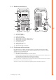
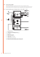
2.3 Machine introduction 1. CHANNEL 10. 3. 2. 6,3A 4. 11. 7. 6. 5. 1. 2. 3. 4. 5. 6. 7. 8. 9. 10. 11. 2.4 8. V 9. EN Control panel X 37 Main switch (ON/OFF) Power on pilot lamp Overheating pilot lamp Welding cable connection, negative pole (–) Welding cable connection, positive pole (+) Control cable connection Fuse (delayed 6.
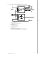
2.5 Connecting cables NOTE! Always check before use that the mains cable, earth return cable and its clamp, interconnection cable and shielding gas hose are in a serviceable condition. Ensure that connectors are correctly fastened. Lose connectors can impair welding performance and damage connectors. 2.5.1 Liquid-cooled system: FastMig X 350 or X 450 + WFX + Cool X 5. 11. 4. V 6. 1. 7. EN 8. 10. V 2. 3. 9. 1. 2. 3. 4. 5. 6. 7. 8. 9. 10. 11.
2.5.2 Air-cooled system: FastMig X 350 or X 450 + WFX 4. 10. 3. V 5. 1. 6. 7. 9. V 2. 8. 1. 2. 3. 4. 5. 6. 7. 8. 9. 10.
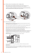
2.5.3 Cable positions for multiple machine configurations When using two or more FastMig X units working on the same work piece, the right positioning of voltage sensing cable and the earth return cable is important. In order for the voltage sensing function to work properly, the earth return cable and the voltage sensing cable for each FastMig X power source should be connected close to each other and away from other units’ cables (see the pictures below). EN 2.5.
2.5.5 Cables Kemppi always recommend the use of high quality copper cables with a suitable crosssectional area. Cable size should be selected depending on the intended welding application. 50 mm² copper cables may be used for low duty work in basic or synergic 1-MIG. However, using pulsed MIG/MAG process, longer cables, or higher welding power increase the voltage loss, and therefore smaller cross sectional interconnection cables and earth return cables will restrict the welding performance of your machine.
3. OPERATION CONTROL 3.1 Main switch I/O When you turn the on/off switch into position I, the pilot warning lamp is illuminated and the machine is ready for use. Always turn the machine on and off with the power source mains switch. Never use the mains plugs as a switch. 3.2 Pilot lamps The pilot lamps of the machine report its operational state: When the green pilot lamp is on, it indicates that the machine is switched on and ready for use.
4. CONTROL PANEL X 37 FastMig X power sources feature X 37 control panel with a clear and logical LCD menu display. The menu allows the operator to refine, adapt and manage the arc process and system function before, during and after welding. The following information details control panel layout, button functions, operation and setup. The menu options and their descriptions are listed for each menu command. 4.1 Layout and button functions 1. 2. 7. 8. 4. EN CHANNEL INFO F1 3.
3. MENU button This button takes you to the main menu list. Proceed following the instructions on screen.
4.2 Using the menus 4.2.1 Selecting the interface language The default menu language is English. If you want to select another menu language, do the following: 1. Connect the mains power and switch on the power source at the main switch. • If this is the initial system activation (if SYSTEM OFF text is in the display), you may need to press and hold the POWER ON button in the to left corner of the X 37 control panel. Hold the button down for 5 seconds. 2.
4.2.4 Creating the first MMA/CC/CV memory channel If you are starting with a new FastMig X power source that contains no MMA/CC/CV memory channels, follow these steps to create the first MMA/CC/CV memory channel. 1. Press MENU button to display the main menu. 2. With up and down arrows, browse to MMA/CC/CV Mode (7/7) and press SELECT. • MMA/CC/CV Mode view appears 3. With the control knob, select ON and press SELECT. • An empty MMA/CC/CV memory channel appears. 4.
1-MIG WFSpeed WFS-Max WFS-Min FineTuning 0.7…25 m/min * Sets the wire feed speed. Changes by steps of 0.05, when WFSpeed < 5 m/min, and by 0.1, when WFSpeed > 5 m/min Sets the limit for maximum WFSpeed Sets the limit for minimum WFSpeed -9.0 … +9.0 FineTuningMax -9.0 … +9.0 FineTuningMin -9.0 … +9.0 -9 … +9 Dynamics Factory setting is 0.0 Adjusts the arc voltage of the curve (arc length) within ( = curve point) certain limits Step: 0.5 Sets the limit for maximum arc length Step: 0.
WISEROOT+ WFSpeed WFS-Max WFS-Min FineTuning 1.5…8.0 m/min * Sets the wire feed speed. Changes by steps of 0.05, when WFSpeed < 5 m/min, and by 0.1, when WFSpeed > 5 m/min Sets the limit for maximum WFSpeed Sets the limit for minimum WFSpeed -9.0 … +9.0 FineTuningMax -9.0 … +9.0 FineTuningMin -9.0 … +9.0 Factory setting is 0.0 Adjusts the base current of the curve (heat of the arc) ( = curve point) within certain limits. Step: 0.5 Sets the limit for maximum heat of the arc Step: 0.
CV PROCESS 4.4 Voltage VoltageMax VoltageMin Dynamics 10…50 V Welding voltage 10…50 V Set the limit for maximum voltage value 10…50 V Set the limit for minimum voltage value -9…+9 Factory setting is 0 Controls the short circuit behaviour of the arc. The lower the value the softer the arc is. The higher the value the rougher the arc is.
ADVANCED FUNCTIONS EN 18 WisePenet Penet%(123A) ON, OFF WiseFusion WiseFusion% ON, OFF 10…60 % or CURVE Factory setting is CURVE When WiseFusion is ON, it controls the amount of short circuits in the arc. The lower the value, the less short circuits in the arc, and the higher the value, the more short circuits in the arc.
SYSTEM CONFIG MENU Water Cooling ON, OFF, AUTO Factory setting is AUTO Water cooler control. ON: Water cooler is always ON OFF: Water cooler is always OFF AUTO: Water cooler starts when welding starts and turns off after a delay when welding stops. Cable Length 10…100 m Step: 5 Factory setting is 10m Welding cable loop length setting for optimising arc control. FineCalib 0V/100A…10V/100A Step: 0.1 V Fine Tuning Calibration Point. Compensation Factory setting is 1.
EN Pre Gas Time 0.0…9.9 s, CURVE. Step: 0.1 Factory setting is CURVE CURVE: Pre Gas time is read from the Welding program. 0.0 – 9.9s: User Pre Gas time setting. Post Gas Time 0.0…9.9 s, CURVE. Step: 0.1 Factory setting is CURVE CURVE: Post Gas time is read from the Welding program. 0.0 – 9.9s: User Post Gas time setting. Control * USER, PANEL, REMOTE, GUN. Factory settings is USER This setting affects the XF 37 (or XF 38) control panel remote control unit selection.
ADMINISTRATOR MENU Change PIN Code Ask PIN 4.5 OFF, StartUp, Menu Factory PIN code is 0000 Administrator pin code change. Factory setting is OFF PIN code inquiry selection OFF: No PIN code inquiry. StartUp: Control panel X 37 always asks for the PIN code when the machine is turned on. Wire feeder panel XF 37 (or XF 38) is not affected and always works without PIN.
4.6 Welding software delivery profile Connected to Kemppi's WFX wire feed units, FastMig X power sources make a very efficient, multi-process welding system. After delivery and installation, your system will include welding software specified at the point of order. If your welding needs change and you wish to update your FastMig X system in the future, you can order additional welding programs or Wise™ and Match™ welding software and load them to your system with Kemppi DataGun field programming device.
High spatter volume • • • • • • • • • • Err1 Power source is not calibrated or calibration data cannot be read • Restart power source • if the problem continues after multiple startups contact Kemppi service representative Err 3 Overvoltage in the mains supply • Check the mains voltage Err 4 Power source is overheated • Do not shut down, let the fans cool the machine. • Check ventilation. • If cooling fans are not running, contact Kemppi service representative.
MEMORY ERROR Machine cannot complete read or write functions on the wire feeder memory card • Check the cables and connections. • Contact Kemppi service representative. SYSTEM BUS ERROR Control panel cannot establish a connection to the CAN bus • Check the flat cables and the control panels. • Contact Kemppi service representative. LICENSE FILE ERROR Machine cannot read wire feeder memory lisence file • Check the cables and connection. • Contact Kemppi service representative.
7. MAINTENANCE When considering and planning routine maintenance, please consider the frequency of machine use and the working environment. Correct operation of the machine and regular maintenance will help you avoid unnecessary downtime and equipment failure. NOTE! Disconnect the machine from the mains before handling the electrical cables. 7.1 Daily maintenance • Check the overall condition of the welding gun. Remove welding spatter from the contact tip and clean the gas nozzle.
7.3 Service Workshop maintenance Kemppi Service Workshops complete maintenance according to their Kemppi service agreement. The major points in the maintenance procedure are listed as follows: • Cleaning of the machine • Checking and maintenance of the welding tools • Checking of connectors, switches and potentiometers • Checking of electric connections • Checking of mains cable and plug • Damaged parts or parts in bad condition are replaced by new ones • Maintenance testing.
9.
Interconnection cables, liquid-cooled FASTMIG X 70-1.8-WH 1.
Remote control unit R30 DataRemote 10 m 618542001 Remote control extension cable 10 m 6185481 Software installation device DataGun 6265023 NOTE! WiseRoot+™ and WiseThin+™ welding processes are not available with SuperSnake sub feeder. 10. TECHNICAL DATA FastMig Connection voltage 3~50/60 Hz Rated power 60 % ED X 350 X 450 400 V, -15…+20 % 400 V, -15…+20 % 22.1 kVA 80 % ED 16.0 kVA 100 % ED 15.3 kVA 16.
KEMPPI OY Kempinkatu 1 PL 13 FIN-15801 LAHTI FINLAND Tel +358 3 899 11 Telefax +358 3 899 428 export@kemppi.com www.kemppi.com Kotimaan myynti: Tel +358 3 899 11 Telefax +358 3 734 8398 myynti.fi@kemppi.com KEMPPI SVERIGE AB Box 717 S-194 27 UPPLANDS VÄSBY SVERIGE Tel +46 8 590 783 00 Telefax +46 8 590 823 94 sales.se@kemppi.com KEMPPI NORGE A/S Postboks 2151, Postterminalen N-3103 TØNSBERG NORGE Tel +47 33 346000 Telefax +47 33 346010 sales.no@kemppi.