WFX 200, 300 200 P Fe, 300 P Fe 200 P Ss, 300 P Ss 200 AMC, 300 AMC 200-T, 300 P-T, 300-T Operating manual EN Brugsanvisning DA Gebrauchsanweisung DE Manual de instrucciones ES Käyttöohje FI Manuel d’utilisation Manuale d’uso FR IT Gebruiksaanwijzing NL Bruksanvisning NO Instrukcja obsługi PL Manual de utilização PT Инструкции по эксплуатации RU Bruksanvisning SV 操作手册 ZH
OPERATING MANUAL English
CONTENTS 1. Introduction.................................................................................................. 3 General. ............................................... . . . . . . . . . . . . . . . . . . . . . . . . . . . . . . . . . . . . . . . . . . . . . . . . . . . . . . . . . . . . . . . . . . . . . . . . . . . . . . . . . . . . . . . . 3 About WFX wire feeders. .............. . . . . . . . . . . . . . . . . . . . . . . . . . . . . . . . . . . . . . . . . . . . . . . . . . . . . . . . .
1. INTRODUCTION 1.1 General Congratulations on choosing the Kemppi WFX welding equipment. Used correctly, Kemppi products can significantly increase the productivity of your welding, and provide years of economical service. This operating manual contains important information on the use, maintenance and safety of your Kemppi product. The technical specifications of the equipment can be found at the end of the manual.
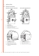
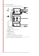
2. INSTALLATION 2.1 Machine introduction WFX 300 P Fe, WFX 300 P Ss, WFX 300 P-T WFX 300, WFX 300 AMC, WFX 300-T 2. 2. 1. 1. 6. EN 4. 5. 3. 4. 5. 1. 2. 3. 4. 5. 6. 3. Control panel ON/OFF button Euro gun connection Voltage sensing cable connection Remote control connection Sub-feeder sync connector (kit optional) 7. 7. 8. 8. 9. 9. 10. 10. 11. 7. 8. 9. 10. 11.
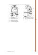
WFX 200, WFX 200 P Fe, WFX 200 P Ss, WFX 200 AMC and WFX 200-T 1. 6. 5. 9. 3. 7. 4. 2. 8. 1. 2. 3. 4. 5. 6. Control panel Remote control connector Voltage sensing cable connection Euro gun connector Shielding gas connection Connection for control cable © Kemppi Oy / 1736 7. 8. 9.
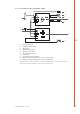
2.2 Connecting cables 2.2.1 Liquid-cooled system: FastMig X + WFX + Cool X 5. 11. 4. V 6. 1. 7. 8. 10. V 2. EN 3. 9. 1. 2. 3. 4. 5. 6. 7. 8. 9. 10. 11.
2.2.2 Air-cooled system: FastMig X + WFX 4. 10. 3. V 5. 1. 6. 7. 9. V 2. 8. 1. 2. 3. 4. 5. 6. 7. 8. 9. 10.
2.3 Assembly of MIG/MAG system Assemble the units in the order mentioned below. Follow the additional mounting and operation instructions delivered with each package. 1. Installation of power source Read and follow the installation instructions given in the FastMig power source operating manual. 2. Mounting of power sources to transport cart Read and follow the instructions given in the transport cart assembly instructions. 3.
2.6 Mounting and locking of wire spool EN NOTE! Check that in filler wire spool is correctly mounted and locked into position. Ensure the spool is not damaged or deformed in such a way that it can rub or chaff against the internal surface of the wire feed unit chassis or door. This may result in increased drag, impacting on weld quality. This may also result in long term wire feed unit damage, rendering the unit unserviceable or unsafe to use. 2.
2.8 GT04 wire feed mechanism This is used in WFX 300 P Fe, WFX 300 P Ss and WFX 300 P-T wire feeders. Wire guide tubes Al, Ss (Fe, Mc, Fc) plastic Fe, Mc, Fc metal EN 10 ø mm outlet tube middle tube inlet tube 0.6 SP007285 SP007273 SP007293 0.8 – 0.9 SP007286 SP007274 SP007294 1.0 SP007287 SP007275 SP007295 1.2 SP007288 SP007276 SP007296 1.4 SP007289 SP007277 SP007297 1.6 SP007290 SP007278 SP007298 2.0 SP007291 SP007279 SP007299 2.4 SP007292 SP007280 SP007300 0.
Wire feed rolls, plastic Fe, Ss, (Al, Mc, Fc) V-groove Fc, Mc, (Fe) V-groove, knurled Al, (Fc, Mc, Ss, Fe) U-groove ø mm lower upper 0.6 W001045 W001046 0.8 – 0.9 W001047 W001048 1.0 W000675 W000676 1.2 W000960 W000961 1.4 W001049 W001050 1.6 W001051 W001052 2.0 W001053 W001054 2.4 W001055 W001056 1.0 W001057 W001058 1.2 W001059 W001060 1.4 – 1.6 W001061 W001062 2.0 W001063 W001064 2.4 W001065 W001066 1.0 W001067 W001068 1.2 W001069 W001070 1.
2.9 DuraTorque™ 400, 4-wheel wire feed mechanism This is used in WFX 200, WFX 200 P Fe, WFX 200 P Ss, WFX 200 AMC, WFX 300, WFX 300 AMC, WFX 200-T and WFX 300-T wire feeders. Wire guide tubes Ss, Al, (Fe, Mc, Fc) plastic EN Fe, Mc, Fc metal ø mm outlet tube middle tube inlet tube 0.6 SP007437 SP007429 SP007293 0.8 – 0.9 SP007438 SP007430 SP007294 1.0 SP007439 SP007431 SP007295 1.2 SP007440 SP007432 SP007296 1.4 SP007441 SP007433 SP007297 1.6 SP007442 SP007434 SP007298 2.
Wire feed rolls, plastic Fe, Ss, (Al, Mc, Fc) V-groove Fc, Mc, (Fe) V-groove, knurled Al, (Fc, Mc, Ss, Fe) U-groove ø mm lower upper 0.6 W001045 W001046 0.8 – 0.9 W001047 W001048 1.0 W000675 W000676 1.2 W000960 W000961 1.4 W001049 W001050 1.6 W001051 W001052 2.0 W001053 W001054 2.4 W001055 W001056 1.0 W001057 W001058 1.2 W001059 W001060 1.4 – 1.6 W001061 W001062 2.0 W001063 W001064 2.4 W001065 W001066 1.0 W001067 W001068 1.2 W001069 W001070 1.
2.10 Adjustment of pressure arms Adjust the drive pressure to the filler wire with the thumb screws mounted over the pressure arms. Notice the graduated scales indicating load. The load applied should be sufficient to overcome a light braking force applied by hand to the filler wire, as it exits the welding gun contact tip. For smaller diameter and soft filler wires, less feed pressure is required.
2.14 Shielding gas NOTE! Handle shielding gas bottle with care. Assess the risks associated with handling and using compressed gas. Always use a cylinder transport carriage and secure the cylinder safely. There are many different suppliers of quality shielding gases for welding. Please ensure that you are selecting the correct gas for your application. FastMig products use welding programs for synergic and pulsed welding. These programs are created and recommend against a particular shielding gas.
2.15 Main switch I/O When you turn the main switch of the FastMig power source into I-position, the pilot lamp closest to this switch will illuminate, indicating the power source is ready for welding. The equipment will return to the same operation state where it was before the last shutdown. Always start and switch off the machine with the main switch, never use the mains plug as a switch. 2.
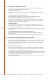
3.2 Layout NOTE! The button layout is the same in both, XF 37 and XF 38 panels. 2. 1. 3. 4. 10. 11. CH REMOTE CHANNEL 4T 2T PANEL 241 W007 XF 37 5. 6. 1. 2. 3. 4. 5. 6. 7. 8. 9. 10. 11. 7. 8. EN 9.
3.3.2 Dynamics button (2) Short press: Dynamics setting for 1-MIG, synergic MIG and CC/CV. ArcForce setting for MMA. Long press: Wire feeder number selection. If there is more than one wire feeder connected to the system, you can select which of them is active. Each wire feeder has its own number (1–3). NOTE! Wire feeder number is not available in MMA, CC and CV processes. 3.3.3 Gas test button (3) CH REMOTE CHANNEL 4T 2T PANEL 241 W007 This button displays the gas test time.
3.3.8 Extra functions button (8) H REMOTE CHANNEL 4T 2T PANEL 241 W007 XF 37Crater fill or Hot start function. Short press: Selects Long press: Turns MMA/CC/CV mode ON/OFF. 3.3.9 Remote Selection Button (9) 4T 2T PANEL 241 W007 XF 37 Short press: Toggles the control between the control panel, gun remote control unit and hand-held remote control unit. EN NOTE! If RemoteAutoRecog setting is ON in X 37 control panel, you can select only those remote controls, which can be found in the system.
3.4 Welding software The FastMig WFX wire feeders are compatible with the following modified welding processes and functions • WiseRoot+™ is a modified welding process for open gap root welding without backing. • WiseThin+™ is a modified welding process developed especially for efficient welding for thin sheets and position welding, also with the CO2 shielding gas. • WiseFusion™ is a welding function for ensuring consistent weld quality in all positions.
PIPE STEEL PACK Group Material Wire ø (mm) Shielding gas Process Number Fe Fe 0.8 Ar+15–25%CO₂ WiseRoot+ F01 Fe Fe 0.9 Ar+15–25%CO₂ WiseRoot+ F02 Fe Fe 1.0 Ar+15–25%CO₂ WiseRoot+ F03 Fe Fe 1.2 Ar+15–25%CO₂ WiseRoot+ F04 Fe Fe 0.8 CO₂ WiseRoot+ F21 Fe Fe 0.9 CO₂ WiseRoot+ F22 Fe Fe 1.0 CO₂ WiseRoot+ F23 Fe Fe 1.2 CO₂ WiseRoot+ F24 Fe Fe Metal 1.2 Ar+15–25%CO₂ WiseRoot+ M04 Fe Fe Metal 1.2 CO₂ WiseRoot+ M24 Fe Fe 0.
WORK PACK EN Group Material Wire ø (mm) Shielding gas Process Number Al AlMg5 1.2 Ar Pulse/Double Pulse A02 Al AlSi5 1.2 Ar Pulse/Double Pulse A12 Fe Fe 1.0 Ar+15–25%CO₂ Pulse/Double Pulse F03 Fe Fe 1.2 Ar+15–25%CO₂ Pulse/Double Pulse F04 Ss CrNiMo 19 12 1.0 Ar+2%CO₂ Pulse/Double Pulse S06 Ss CrNiMo 19 12 1.2 Ar+2%CO₂ Pulse/Double Pulse S04 Al AlMg5 1.2 Ar 1-MIG A02 Al AlSi5 1.2 Ar 1-MIG A12 Fe Fe 0.9 Ar+15–25%CO₂ 1-MIG F02 Fe Fe 1.
STAINLESS STEEL PACK Group Material Wire ø (mm) Shielding gas Process Number Ss CrNiMo 19 12 0.8 Ar+2%CO₂ Pulse/Double Pulse S01 Ss CrNiMo 19 12 0.9 Ar+2%CO₂ Pulse/Double Pulse S02 Ss CrNiMo 19 12 1.0 Ar+2%CO₂ Pulse/Double Pulse S06 Soft Ss CrNiMo 19 12 1.2 Ar+2%CO₂ Pulse/Double Pulse S04 Ss CrNiMo 19 12 1.0 Ar+He+CO₂ Pulse/Double Pulse S26 Soft Ss CrNiMo 19 12 1.2 Ar+He+CO₂ Pulse/Double Pulse S24 Ss CrNiMo 19 12 0.8 Ar+2%CO₂ 1-MIG S01 Ss CrNiMo 19 12 0.
3.5 EN Arc voltage display FastMig X is capable of measuring and showing the voltage close to the welding arc. By taking this feature into use you don't need to be concerned about the voltage losses in welding cables anymore. With this feature you are only required to set the voltage for the arc before welding and after welding you can see the voltage close to the arc. In order to use the arc voltage feature, follow these steps: 1.
4. BASIC TROUBLESHOOTING NOTE! The problems listed and the possible causes are not definitive, but serve to suggest some standard and typical situations that may present during normal environmental use when using the MIG/MAG process with FastMig X 350 or X 450 and WFX wire feeders.
EN Err1 Power source is not calibrated or calibration data cannot be read • Restart power source • if the problem continues after multiple startups contact Kemppi service representative Err 3 Overvoltage in the mains supply • Check the mains voltage Err 4 Power source is overheated • Do not shut down, let the fans cool the machine. • Check ventilation. • If cooling fans are not running, contact Kemppi service representative.
5. MAINTENANCE When considering and planning routine maintenance, please consider the frequency of machine use and the working environment. Correct operation of the machine and regular maintenance will help you avoid unnecessary downtime and equipment failure. NOTE! Disconnect the machine from the mains before handling the electrical cables. 5.1 Daily maintenance • Check the overall condition of the welding gun. Remove welding spatter from the contact tip and clean the gas nozzle.
6. DISPOSAL OF THE MACHINE Do not dispose of electrical equipment with normal waste! In observance of European Directive 2002/96/EC on waste electrical and electronic equipment, and its implementation in accordance with national law, electrical equipment that has reached the end of its life must be collected separately and taken to an appropriate environmentally responsible recycling facility.
Interconnection cables, liquid-cooled FASTMIG X 70-1.8-WH 1.
Accessories Cooling unit Cool X EN 6068200 SuperSnake GT02S sub feeder 10 m 6153100 SuperSnake GT02S sub feeder 15 m 6153150 SuperSnake GT02S sub feeder 20 m 6153200 SuperSnake GT02S sub feeder 25 m 6153250 SuperSnake GT02S W sub feeder 10 m 6154100 SuperSnake GT02S W sub feeder 15 m 6154150 SuperSnake GT02S W sub feeder 20 m 6154200 SuperSnake GT02S W sub feeder 25 m 6154250 SuperSnake GT02S sub feeder synchronization unit for WFX 300 series wire feeders W004030 KV 200 mounting
MIG guns PMT MN 1.2 mm / 60° / L198 / ROOT 3.5 m 62503230N04 PMT MN 1.2 mm / 60° / L168 / ROOT 3.5 m 62503230N06 PMT MN 1.2 mm / 60° / L198 / ROOT 5m 62503250N04 PMT MN 1.2 mm / 60° / L198 3.5 m 62503230N08 PMT MN 1.2 mm / 60° / L198 5m 62503250N08 PMT MN 1.2 mm / 45° / L222 3.5 m 62503230N02 PMT MN 1.2 mm / 45° / L222 5m 62503250N02 PMT MN 1.0 mm / Ss / 60° / L198 / ROOT 5m 62503250N03SS PMT MN 1.0 mm / Ss / 60° / L198 5m 62503250N07SS PMT MN 1.
8. TECHNICAL DATA WFX 200, 200 P Fe, 200 P Ss, 200-T, 200 AMC 300 P Fe, 300 P Ss, 300 P-T 300, 300-T, 300 AMC Operating voltage (safety voltage) Rated power Output 40 °C 50 V DC 50 V DC 50 V DC 100 W 250 W 100 W 60 % ED 520 A 520 A 520 A 100 % ED 440 A 440 A 440 A 1 – 25 m/min 0.5 – 25 m/min 1 – 25 m/min 4-roll 4-roll, two motors 4-roll 32 mm 32 mm 32 mm 0.6 – 1.6 mm 0.6 – 2.0 mm 0.6 – 1.6 mm ø Cored wire 0.8 – 2.0 mm 0.8 – 2.4 mm 0.8 – 2.0 mm ø Al 0.8 – 2.4 mm 0.8 – 2.
KEMPPI OY Kempinkatu 1 PL 13 FIN-15801 LAHTI FINLAND Tel +358 3 899 11 Telefax +358 3 899 428 export@kemppi.com www.kemppi.com Kotimaan myynti: Tel +358 3 899 11 Telefax +358 3 734 8398 myynti.fi@kemppi.com KEMPPI SVERIGE AB Box 717 S-194 27 UPPLANDS VÄSBY SVERIGE Tel +46 8 590 783 00 Telefax +46 8 590 823 94 sales.se@kemppi.com KEMPPI NORGE A/S Postboks 2151, Postterminalen N-3103 TØNSBERG NORGE Tel +47 33 346000 Telefax +47 33 346010 sales.no@kemppi.