
Operation Manual


8
A7 MIG Welder© Kemppi Oy 2018 1804
INTEGRATION GUIDE
Filler wire
Connect the wire liner to the ller wire inlet
connector on the rear of the wire feeder. Connect
the other end of the wire liner to the wire drum or
spool, and run the wire up to the wire feeder either
manually or by using wire inch functionality at the
wire drum.
Peripheral connector
For a push-pull welding torch, a collision sensor, and other
peripheral devices, the wire feeder has a common 10-pin
peripheral connector at the front of the wire feeder. The
connections of the push-pull torch and the peripherals are
described later in this document.
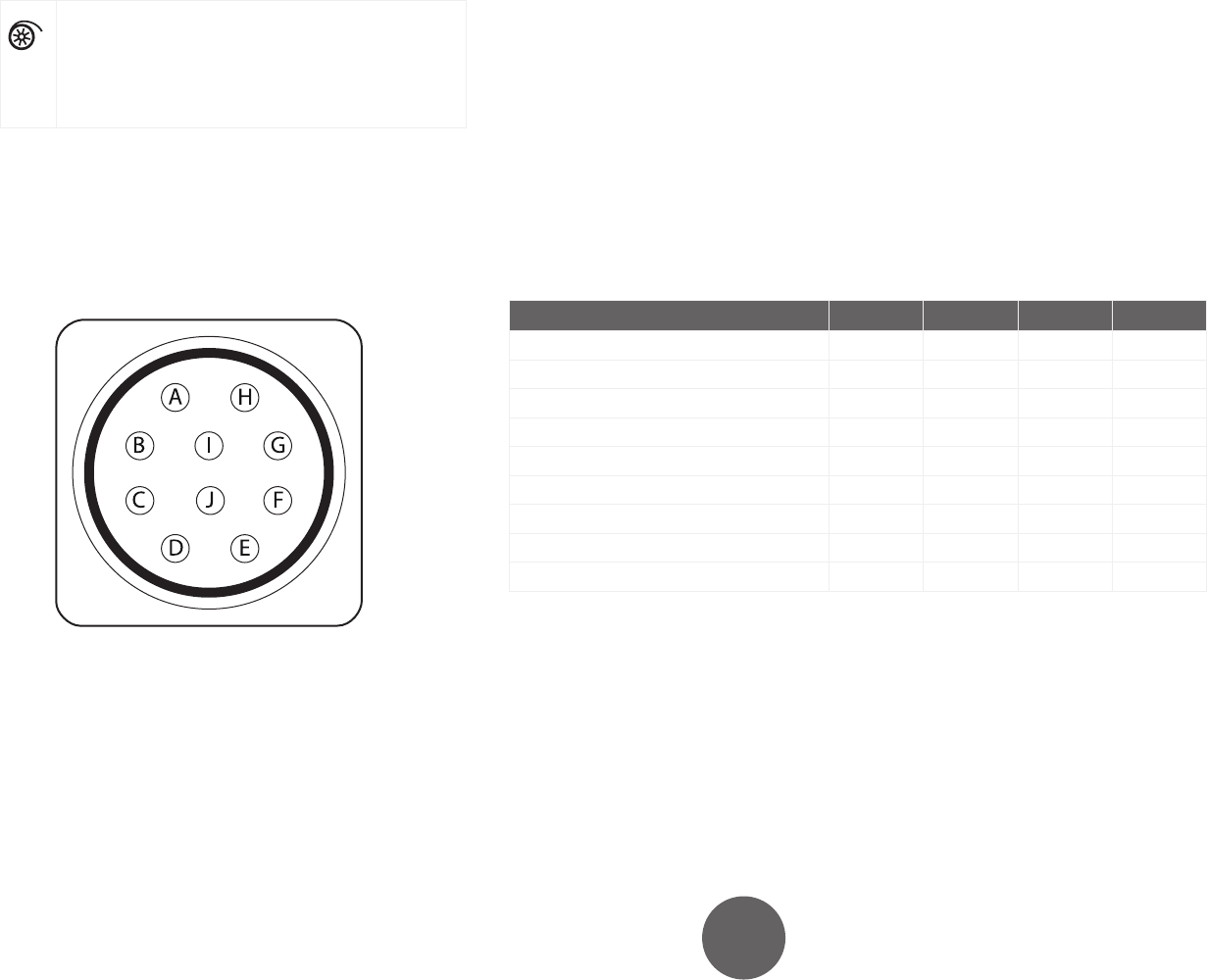
Figure 3.3: Peripheral connector pinout
A. Motor (+)
B. Motor (–)
C. Supply (+24 V)
D. Wire inch input
E. Collision sensor input
F. Touch sensor output for gas nozzle (+50…+200 V)
G. Tachometer (+5 V)
H. Supply GND
I. Tachometer GND
J. Tachometer input
Table 3.1: Electrical characteristics for the peripheral supplies
Value Min. Typical Max. Unit
Motor supply voltage (RMS) 24 48 V
Motor supply voltage (peak) 75 V
Motor supply current 0 5 A
Supply voltage 23.0 24.0 24.5 V
Supply current 0 150 780* mA
Tachometer supply voltage 4.9 5 5.1 V
Tachometer supply current 120 125 130* mA
Touch sensor output voltage** 50 200 V
Touch sensor output current** 10 mA
* This is the short-circuit current.
** The touch sensor electrical characteristics are found in
the A7 MIG Welder Operating manual.