
Operation Manual


54
A7 MIG Welder© Kemppi Oy 2018 1804
INTEGRATION GUIDE
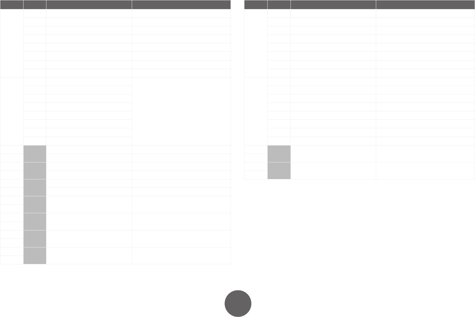
6.3.6 CUST1: Customer-specific table
Interface mode = 3. Table size = 16 bytes.
Byte Bit Control (Robot -> Welder) Status (Welder -> Robot)
0 0 StartWelding ArcOn (1)
1 WeldingAllowed AutoManual
2 OnlineControl CycleOn
3 (Not in use) ArcOn (2)
4 (Not in use) CollisionDetected
5 DigitalOutput1 Error
6 DigitalOutput2 Ready
7 DigitalOutput3 TouchSensed
1 0 GasBlow
ErrorNumber
1 WireInch
2 WireRetract
3 (Not in use)
4 TouchSensorOn
5 (Not in use)
6 (Not in use)
7 (Not in use)
2
MemoryChannel (Not in use)
3 (Not in use) (Not in use)
4
(Not in use) (Not in use)
5 (Not in use) (Not in use)
6
(Not in use) (Not in use)
7 (Not in use) (Not in use)
8
WireFeedSpeed WeldingCurrent
9
10
Voltage / FineTuning WeldingVoltage
11
12
(Not in use) (Not in use)
13
14
(Not in use) (Not in use)
15
6.3.7 CUST2: Customer-specific table
Interface mode = 5. Table size = 6 bytes.
Byte Bit Control (Robot -> Welder) Status (Welder -> Robot)
0 0 StartWelding ArcOn
1 AirBlow Error
2 GasBlow GasFlowOK
3 WireInch DigitalInput2 (Wire OK)
4 WireRetract AutoManual
5 DigitalOutput3 LocalRemote
6 OnlineControl Ready
7 DigitalOutput2 (Cleaning on) DigitalInput3 (Cleaning OK)
1 0 TouchSensorOn TouchSensed
1 MemoryChannel (bit 0) DigitalInput1
2 MemoryChannel (bit 1) DigitalInput4
3 MemoryChannel (bit 2) DigitalInput5
4 MemoryChannel (bit 3) PowerSourceReady
5 MemoryChannel (bit 4) CycleOn
6 MemoryChannel (bit 5) (Not in use)
7 MemoryChannel (bit 6) (Not in use)
2
WireFeedSpeed WeldingCurrent
3
4
Voltage / FineTuning WeldingVoltage
5